Technical data
Manuals
Brands
Esoteric Manuals
DVD Player
DV-30s
37
38
39
40
41
42
43
44
45
46
Manual No. 405/0101
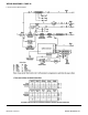
WIRING DIAGRAMS
41
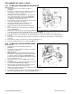
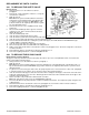
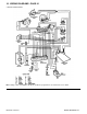
10. WIRING DIAGRAMS - PAGE 41
a. Illustrated wiring diagram
Note:
Always set the Test Switch to the O (off) position if a programmer is used before the case is fitted.
1
...
...
39
40
41
42
43
...
...
46