
Technical data

37 REPLACEMENT OF PARTS Manual No. 405/0101
REPLACEMENT OF PARTS - PAGE 37
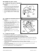
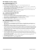
9.19 TO REPLACE THE DIVERTER VALVE HEAD
Refer to Fig. 42.
1. Gain general access as described in section 9.1,
paragraph 1.
2. Remove the screw securing the control box, see Fig. 25
and lower the control box. To gain extra clearance,
disengage the control box hinge pins.
3. Note the position of the manual lever on the right hand
side of the diverter valve, then move it to 'MAN OPEN'
(top position). Slacken the screw at the left hand side
securing the cover and lift off the cover.
4. Remove the two screws securing the diverter valve head
to the main body and lift off the head.
5. Disconnect the diverter valve head wires from the
terminal block on the top of the control box.
6. Cut the new diverter valve head lead to match the old
one.
7. Move the manual lever on the side of the new diverter
valve to 'MAN OPEN'.
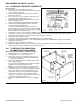
Fig. 42
8. Fit the diverter valve head to the valve body (operating lever at the right hand side), ensuring that the shaft seats
correctly. Secure the head in position with the two new screws supplied.
9. Move the manual lever on the right hand side of the new diverter valve to the original position of the old one.
10. Connect the diverter valve head wires to the terminal block on the top of the control box. See wiring diagram on
page 41.
11. Re-engage the control box hinge pins and raise the control box securing it in position with the screw previously
removed.
12. Reassemble the boiler as described in section 9.2, paragraphs 6 to 9.
13. Refer to the Lighting Instructions, section 8 and light the boiler.
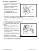
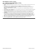
9. 20 TO REPLACE THE PRESSURE GAUGE
Refer to Fig. 43.
1. Gain general access as described in section 9.1,
paragraph 1.
2. Remove the screw securing the control box, see Fig. 25
and lower the control box.
3. Drain the system.
Note: When the system is drained, filled or vented, the
manual lever on the right hand side of the diverter valve,
see Fig. 27, must be moved to the 'MAN OPEN' (top)
position. Return it to its original position after the system
has been filled and vented.
4. Remove the pressure sensor capillary from the safety
valve body.
5. Compress the clips on the body of the gauge and push it
out of the panel, withdrawing the capillary.
6. Fit the new pressure gauge and connect the sensor to
the safety valve using a new sealing washer.
Fig. 43
7. Fill the system and vent the boiler as described in section 3.16, paragraphs 2 to 5. Check the pressure sensor
connection for water soundness.
8. Reassemble the boiler as described in section 9.2, paragraphs 5 to 9.
9. Refer to the Lighting Instructions, section 8 and light the boiler.