
Technical data

31 REPLACEMENT OF PARTS Manual No. 405/0101
REPLACEMENT OF PARTS - PAGE 31
6. Turn on the gas supply at the gas service cock.
7. If a programmer is used, ensure that the test switch on the top of the control box is set to O (off).
8. Place the outer case front panel in position over the four fixings (two on each side panel) and push the panel back to
engage the fixing pins into the front panel.
9. Carefully slide the bottom panel assembly into position (the bottom panel goes above the returns on the case side
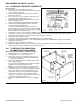
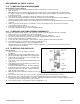
panels), clip the neon, see Fig. 35, into its holder on the back of the control panel as the bottom panel is slid into
position. With the control panel cover open, secure the control panel to the side panels with the two countersunk hd.
screws previously removed.
Note: If a programmer is fitted it will be necessary to connect the programmer wiring harness to the rear of the
programmer as the bottom panel assembly is slid into position.
9.3 TO REPLACE THE SPARK ELECTRODE OR ELECTRODE LEAD
Refer to Fig. 34.
Spark electrode.
1. Gain general access as described in section 9.1.
2. Disconnect the electrode lead from the spark electrode.
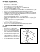
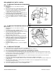
3. Undo the securing nut and remove the electrode, see Fig. 34, from the pilot assembly.
4. Fit the new spark electrode to the pilot assembly securing it in position with the nut.
Check that the spark gap is 5.0 mm ± 2 mm as shown in Fig. 34.
5. Connect the electrode lead to the spark electrode.
6. Reassemble the boiler as described in section 9.2, paragraphs 1 to 9.
7. Refer to the Lighting Instructions, section 8 and light the boiler.
Electrode lead.
1. Gain general access as described in section 9.1.
2. Disconnect the electrode lead from the spark electrode. Fit the protective sleeve over the new lead.
3. Remove the bottom case seal housing channel (lifts off the chassis). Connect the new lead to the spark electrode.
Ensure that the pilot supply and electrode lead are in position in the cut out in the bottom of the chassis and replace the
seal housing channel over the bottom of the chassis, ensure it is pushed fully home.
4. Replace the inner case front cover and expansion vessel as described in section 9.2, paragraphs 1 to 5.
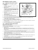
5. Remove the four screws securing the control box front cover and carefully swing down the cover.
Disconnect the electrode lead from the circuit board and withdraw it out of the back of the box. Pass the new electrode
lead through the back of the control box and connect it to the circuit board (fit the grommet on the lead in position in the
hole). Replace the control box front, securing it with the screws previously removed.
6. Replace the outer front panel and bottom panel assemblies as described in section 9.2, paragraphs, 6 to 9.
7. Refer to the Lighting Instructions, section 8 and light the boiler.
9.4 TO REPLACE THE PILOT INJECTOR
Refer to Fig. 34.
1. Gain general access as described in section 9.1.
2. Remove the bottom case seal housing channel (lifts off the chassis).
3. Undo the securing nut and remove the spark electrode, see Fig. 34, from the pilot assembly.
4. Undo the tubing nuts and disconnect the pilot supply from both the pilot assembly and gas valve.
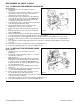
Carefully remove the pilot injector, see Fig. 34.
5. Locate the new pilot injector over the end of the pilot supply, as shown in Fig. 34 and carefully position it in the pilot
burner. Secure the pilot supply to the pilot assembly and gas valve.
6. Replace the spark electrode and check that the spark gap is 5.0 mm ± 2 mm, see Fig. 34.
7. Ensure that the pilot supply and electrode lead are in position in the cut out in the bottom of the chassis and replace the
seal housing channel over the bottom of the chassis, ensure it is pushed fully home..
8. Refer to the Commissioning Instructions, section 4. Light the pilot, check the pilot flame and test the pilot supply for gas
soundness.
9. Reassemble the boiler as described in section 9.2 (ignore paragraph 6).
10. Refer to the Lighting Instructions, section 8 and light the boiler.