
Technical data

Manual No. 405/0101 ANNUAL SERVICE 27
ANNUAL SERVICE - PAGE 27
7.3 CLEANING THE BOILER
1. Brush the heat exchanger from above and below using a suitable brush. Brush back to front NOT sideways. Remove
any fallen deposits from the base of the chassis.
2. Brush the burner top and check that the flame ports are clear. Any blockage may be removed with a fine wire brush.
Turn the burner open end down and tap gently to remove any debris.
3. If the pilot burner requires cleaning, remove the two screws securing it to the burner and remove, clean the burner head
with a fine wire brush then refit it to the main burner.
4. Check the condition of the spark electrode, clean with a fine wire brush if necessary.
5. Unscrew the main injector from the burner manifold (take care not to lose the sealing washer), clean by blowing through
or washing. Do NOT clear the injector with a pin or wire. Clean the pilot injector in a similar manner.
6. Replace the main injector using a small amount of jointing compound - do not forget to fit the sealing weasher.
7. Remove the four screws securing the fan to the turret (make a note which way the fan is fitted). Examine the fan
impellor and carefully clean if necessary. Refit the fan to the turret.
7.4 REASSEMBLE THE BOILER
1. Replace the burner (ensure that it is located over the injector) then the small baffle infront of it using the screws
previously removed.
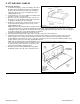
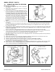
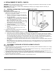
2. Locate the pilot injector over the end of the pilot supply, as shown in Fig. 34 and carefully position it in the pilot burner.
Secure the pilot supply to the pilot assembly and gas valve.
3. Replace the spark electrode and check that the spark gap is 5.0 mm ± 2mm, see Fig. 34.
4. Ensure that the pilot supply and electrode lead are in position in the cut out in the bottom of the chassis and replace the
seal housing channel over the bottom of the chassis, ensure it is pushed fully home.
5. Replace the combustion chamber front cover and secure in position with the four screws previously removed.
6. Replace the flue hood, with the fan assembly retaining returns at the rear. Replace the blanking plates and secure them
to the sides of the flue hood with the four screws previously removed.
Note: On the 80 model these four screws also secure the flue hood to the combustion chamber.
7. All models except 80 - Secure the flue hood to the combustion chamber with the four screws previously removed - two
at the back (extended screws) and two at the front.
8. Reconnect the overheat cut-off device leads (the polarity is not important) and connect the push rod to the cut-off device
(the rubber sleeve locates over the cut-off device button).
9. Ensure that the flue tube sleeve is on the fan outlet and pushed fully home (if the flue tube sleeve was removed, ensure
that the 'O' ring is in position on the fan outlet when replacing the sleeve over the fan outlet). Place the fan assembly on
top of the flue hood with the outlet facing towards the flue and reconnect the leads, see Fig. 14a, as follows:
Two violet leads to the fan motor.
Yellow lead to pressure switch No connection.
Red lead to pressure switch Nc connection.
Black lead to pressure switch C connection.
With the fan assembly resting on the flue hood engage the flue tube sleeve on the fan outlet into the inner tube of the
flue. Ensure that the base of the fan assembly is located under the returns at the rear of the flue hood. (For side exit
flue locate the base of the fan assembly under the returns first then slide the fan across into the flue).
Note: If a Vertex Flue is fitted, slide the flue tube sleeve down out of the flue and over the fan outlet.
Secure the front of the fan assembly to the flue hood with the two screws previously removed.
10. Refer to the Commissioning Instructions, section 4. Light the pilot and check the flame, test the pilot supply for gas
soundness and check the main burner setting pressure.
11. Ensure that the inner case seals are intact and in position in the seal housing channels and that the channels are
correctly located over the sides of the boiler chassis. Replace the inner case front panel (expansion vessel frame fixing
brackets nearest the top), securing it in position with the four screws previously removed.
Tighten sufficiently to form a seal.
12. Remove the split pins from the ends of the tie rods and unhook them from the support frame, raise the expansion vessel
assembly and secure the frame to the inner case front panel using the two screws previously removed.
13. Unhook the tie rods from the sides of the boiler, replace the split pins into the rods and position them in the retaining
clips on the front of the expansion vessel frame.
14. Raise the control box and secure in position with the screw previously removed.