
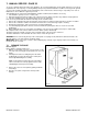
Technical data

Manual No. 405/0101 FIT THE CASE 23
5. FIT THE CASE - PAGE 23
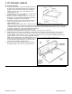
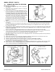
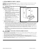
Refer to Figs. 29 and 30.
1. Locate the side panel(s) over the two fixings at the side of
the boiler chassis against the wall. Secure each panel in
position to the front of the boiler, at the top and bottom,
using two of the No.8 x 12 lg. countersunk hd. screws
supplied with the boiler.
2. If a programmer is used, ensure that the test switch on the
top of the control box is set to O (off).
3. Place the outer case front panel in position over the four
fixings (two on each side panel) and push the panel back
to engage the fixing pins into the front panel.
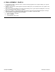
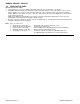
4. Position the control panel as shown in Fig. 30 and secure
it to the bottom panel using three No.6 x 10 lg. screws
supplied with the boiler.
Fig. 29
Note: If the optional programmer kit is to be fitted, push out the blanking panel, see Fig. 30, from the back of the
control panel before it is secured to the bottom panel and bracket. Fit the programmer to the back of the control panel,
locating the top two hinge pins into the brackets above the opening then lowering it against the panel and securing it at
the bottom using the two screws supplied with the programmer..
Retain the Programmer instructions to hand to the User.
5. Ensure that the boiler thermostat control knob is in position on the front of the control box.
6. Carefully slide the bottom panel assembly into position (the bottom panel goes above the returns on the case side
panels), clip the neon, see Fig. 28, into its holder on the back of the control panel as the bottom panel is slid into
position. With the control panel cover open, secure the control panel to the case side panels with the two M4 x 10 lg.
countersunk hd. screws (one each side) supplied with the boiler.
Note: If the programmer kit has been fitted it will be necessary to connect the programmer wiring harness
to the rear of the programmer and to the 6-way socket on
the left hand side of the control box, see Fig. 25, as the
bottom panel assembly is slid into position.
7. Stick the relevant model identification label (supplied in
the literature pack) to the rear of the control panel cover.
Fig. 30