
Technical data

18 INSTALLATION Manual No. 405/0101
INSTALLATION - PAGE 18
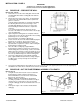
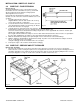
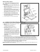
3.13 CONNECT THE GAS SUPPLY
Refer to Fig. 24.
Connect a 15 mm gas supply, using a suitable adaptor, to the
service cock.
It is recommended that a 22 mm supply be used for the 80
model.
Note: The gas supply must be from below, as the boiler
chassis extends below the service cock, see Fig. 2.
Do not turn the gas supply on at this stage.
Fig.24
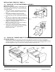
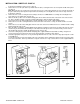
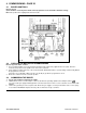
3.14 CONNECT THE POWER SUPPLY CABLE
Refer to Fig. 25.
1. Remove the five screws securing the control box and its
front cover, carefully swing down the cover and lower the
control box. Take care not to damage the boiler
thermostat capillary.
2. Two cable clamps are provided on the back of the control
box, use one just for the mains supply and the other for
any other external wiring. Slacken the necessary cable
clamp screws. Feed the power supply cable into the
boiler through the hole (marked 'wiring') in the bottom of
the chassis, then into the control box through a clamp
and connect the wires, brown to L and blue to N on the
terminal block and green and yellow to the earthing screw
( ). Ensure correct polarity.
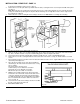
Note: When connecting the power supply cable, ensure
that the length of the earth wire is such, that if the power
supply cable slips out of the cable clamp the live and
neutral wires become taut before the earth wire.
Fig. 25
3. Feed the cylinder thermostat wires, room thermostat wires and any other external controls wiring into the boiler
through the hole (marked 'wiring') in the bottom of the chassis, then into the control box through the other cable clamp
and connect them to the terminal block.
Refer to the tables on page 42 for various room and cylinder thermostat connections.
Note: The cylinder thermostat must be a 240 V type.
4. If the optional programmer kit is not fitted and other external controls are used (e.g. programmer, room thermostat).
The switched live must be connected to terminal ON on the terminal block.
5. Take up excess slack in the power supply cable between the terminal block and the cable clamp, then tighten the
cable clamp screws. Repeat for any wires through the other cable clamp.
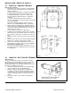
6. Raise the control box and replace the control box front, ensuring that the boiler thermostat capillary is located in the cut
out in the side of the control box. Secure in position with four of the screws previously removed. Check that the control
box can be raised and lowered freely, without straining any of the wiring.
Ensure that all external control cables are secured.
Do not secure the control box in its raised position at this stage.
7. Carry out preliminary electrical system checks i.e. Earth Continuity, Short Circuit, Polarity and Resistance to Earth.
Do not switch on the electricity supply at this stage.