
Technical data

11 INSTALLATION Manual No. 405/0101
INSTALLATION - PAGE 11
IMPORTANT
Sections 3.3 to 3.6 are for rear flue applications.
Sections 3.7 to 3.12 are for side flue applications.
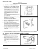
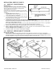
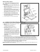
3.3 REAR FLUE - PREPARE THE WALL
Refer to Figs. 8 and 9.
1. Remove the four screws and sealing plate from the wall
mounting plate. Discard the sealing plate but retain the
four screws.
2. Decide upon the position of the boiler, ensuring that the
position of the flue terminal will meet the requirements
given in section 2.6.
Using the wall mounting plate as a template and adding
the following dimensions to the raised edges of the
mounting plate will give the space necessary for the
boiler including the minimum clearances required for
servicing:-
Top 107 mm, Bottom 528 mm, Each side 78 mm.
The side of the white case is 68 mm from the raised edge
of the mounting plate. Fig. 8
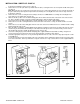
3. Again using the mounting plate as a template mark the
position of the hole for the flue duct and the five mounting
plate fixing holes as shown in Fig. 8.
Ensure the plate is level and the right way up.
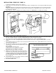
4. Cut the 115 mm dia. hole in the wall and drill and plug the
fixing holes to accept 2½” lg. No.12 woodscrews.
5. Make a note of the finished wall thickness, this is very
important and is required for section 3.4 when cutting the
flue/terminal assembly to length.
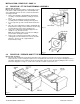
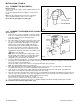
6. Place the rubber sealing ring, supplied with the
flue/terminal assembly, in position in the opening in the
wall mounting plate as shown in Fig. 9, it does not matter
what position the cut-away is in. Ensure that the groove in
it is located correctly over the mounting plate and that the
holes line up with the fixing holes in the mounting plate.
7. Secure the sealing ring in position with the clamping
plate, supplied with the flue/terminal assembly, using the
four M4 x 10 lg. screws previously removed from the
mounting plate.
Fig. 9
8. Secure the mounting plate in position with five 2½” lg. No.12 woodscrews (not supplied). Ensure it is level, the right way up
and that the hole for the flue is centralised over the hole cut in the wall.
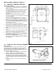
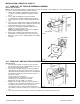
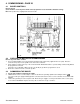
3.4 REAR FLUE - CUT THE FLUE/TERMINAL ASSEMBLY TO LENGTH
Refer to Fig. 10.
1. Using the measurement noted in section 3.3 mark the
flue/terminal assembly so that it is 28 mm plus (+)
finished wall thickness, from the back of the terminal
flange to the end of the tubes.
2. With the cutting jig, supplied with the flue/terminal
assembly, in position over the flue/terminal assembly as
shown in Fig. 10, cut the tubes to the correct length.
Using the cutting jig should ensure that the tubes are cut
square.
3. Clean up the edges of the cut tubes and discard the
cutting jig.
Fig. 10