
User`s guide


Introduction User’s Guide
A.6
Connecting your ESI phone
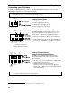
Depending on which ESI phone you have, use the appropriate diagram (below) to connect it. Each
diagram represents the panel on the phone’s underside.
Note: The “Top of phone” and “Bottom of phone” references in these diagrams show the correct vertical
orientation of the phone — i.e., the part with the display is the top.
12-Key Feature Phone
24-Key Feature Phone
• Connects like a basic phone.
• Handset plugs into right-side jack.
• Line cord plugs into left-side jack.
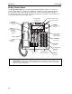
48-Key Digital Feature Phone
In addition to how the 24-Key Feature Phone connects
to the handset and line cord, note the presence of a
headset jack
1
, as well as the following information:
• TAPI version includes a cable for connecting to your
PC’s serial port.
• 60-Key Expansion Console cable (included with each
Console) uses standard RJ-11 telephone connectors.
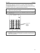
48-Key IP Feature Phone
48-Key Remote IP Feature Phone
In addition to the details mentioned previously for
the 48-Key Digital Feature Phone, each IP Feature
Phone includes:
• A power supply that is unswitched (i.e., always-on AC
outlet) and plugs into the phone.
• An Ethernet cable, which connects the
phone to a PC (or, if no PC is present, directly to a
router, switch or hub) to achieve connectivity to a local
area network (LAN).
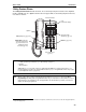
Note: When the phone is in the highest upright position, use the wall-mount hook located under the handset
to secure the handset when you’re not using the phone.
1
On 48-Key Feature Phones shipped by ESI to its Resellers on or after March 1, 2004.
Line cord
to wall
Handset
Connectors on bottom of
48-Key Digital Feature Phone
(headset jack shown)
Line cord
to wall
To 60-Key
Console
Handset
(TAPI)
to PC
To
headset
To 60-Key
Console
Handset
To power
supply
To
PC
To
LAN
To
headset