
User manual


5 INSTALLATION
0463 373 101
- 34 -
© ESAB AB 2015
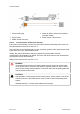
1. Connect the central connector of the cable assembly (2) to the wire feeder cabinet
socket. Tighten the central connector sleeve nut fingertight. Do not use tools!
1. Control cable 5. Return of heated water (red cap)
2. EURO central connector 6. Main drive / feeder
3. Air blow-out 7. Water cooling system
4. Cooling water (blue cap)
2. Connect the water hoses to the cooling circuit (7) in water cooled systems. The end of
the hose marked blue (4) is connected to the water outlet, and the end marked red (5) is
connected to the water return.
3. Connect the blow-out line (3) to the corresponding connection of the feeder.
4. Connect the control line plug (1) to the feeder. See section "Electrical connections".
NOTE!
All hoses and the control line must be installed such that they cannot bend or be
damaged!
5.7.2 Hollow wrist system
5.7.2.1 Feeding through the robot arm
NOTE!
In order to adjust the wire feeder position to the cable assembly length, it must be
mounted on an adjustable support with a possible movement of ± 2-3 cm (± 1
inch) to the back and to the front. The length of the cable assembly must be
determined from the centred mounting position of the wire feeder.
1. Move the robot arm into a completely straight position, see illustration below. Make sure
that (1) axis 6 (rotation around the torch axis) is in 0° position.
2. Move the feeder (3) completely to the back in order to create space for inserting the
cable assembly. If it is not possible to move the feeder sufficiently, it should be removed
from the robot.