
User manual


5 INSTALLATION
0463 373 101
- 19 -
© ESAB AB 2015
5 INSTALLATION
5.1 Preparation
WARNING!
For your own safety, make sure that the robot is either in standby or power-less
state before doing maintenance work in the moving radius of the robot.
The following assembly instructions must be exactly adhered to. Attention is to be paid
during assembly that the cables are not damaged. This can lead to a short circuit, which may
damage the electronics of the robot or the welding torch.
Use only original ESAB components that have been specially developed for this purpose.
Only then can the correct functioning of the whole welding torch system be guaranteed.
Below, the different steps of installation are described in the preferred order, recommended
by ESAB.
CAUTION!
For hollow wrist systems make sure that the clear space around the robot is at
least Ø45 mm (1.8 inch) around the wrist and 50 mm (2.0 inch) near the wire
feeder.
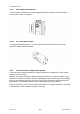
5.2 Installing the adapter flange
1. Position the model-specific adapter flange (2) with the index pin on the robot arm and fix
it with the hexagon socket screws (1) included. The number and type of screws and
index pin may vary depending on the robot model.
NOTE!
Ensure that the index pin is located correctly! The maximum torque of 1.2 Nm
(10.5 lbf in) must be observed for the fastening of the adapter flange screws.
Prevent self-loosening of the screws by using suitable thread locking measures.
5.3 Installing the torch mount
The installation procedure of the torch mount depends on the design of the system together
with the choice of torch mount and safety-off mechanism.
Only torch mounts having a hole pattern coinciding with that of the mounting surface may be
attached.