
Specifications


N7500 ASSEMBLY AND INSTALLATION
ASSEMBLY AND INSTALLATION 4-8 Manual 89250890
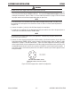
4.06 Remote Pendant Installation
Make the following connections from the Pendant to the Control Box. See "Figure 4-12: Assembly Stage 3".
(Rear panel assembly
not shown for clarity)
N7500 Gouging System
Automatic Control
anel assembly
n for clarity
REMOTE PENDANT
REMOTE PENDANT CABLE
OK
TRV
JOG
STOP
TUNE
ROUGH
START
M
O
T
O
R
C
ABLE -
CO
NTR
O
L B
O
X T
O
T
O
R
C
H HEAD
A
IR H
OSE
D
C
P
O
WE
R
C
ABLE
(
+)
O
UT
TO
R
C
H HEAD
G
ROUND CABLE (–
)
D
C
P
O
WER
C
ABLE (+) IN
INCOMIN
G
AIR
LINE
PO
WE
R
S
UPPL
Y
TORCH HEADPENDANTAIR OUT
M
O
UNTIN
G
FIXTURE
AIR INLET
A
RT# A-10854_A
B
P
OWER SUPPLY
C
OMMUNICATION CABL
E
AIR RE
G
ULAT
O
R
OU
5 AMP
5 AMP
WO
RK PIE
CE
S
I
G
NA
L
WIR
E
G
ROUND CABLE (–)
CO
NTR
O
L B
O
X INP
U
T
AC
P
O
WER
C
ABL
E
CONTROL BOX
(VIEWED FROM CABINET RIGHT SIDE)
120
V
O
R
220
V
THESE CONNECTIONS
ON OTHER SIDES
Figure 4-12: Assembly Stage 3
14. Connect the Remote Pendant Cable Assembly to the Remote Pendant and the Control Box. Cable has a
large 7 pin connector at each end. Refer to "Table 4-7: Cable Identification" on page 4-3.
15. Plug the travel system grounded power cord into the receptacle labeled “POWER OUTLET”.
WARNING
Select the receptacle voltage that correctly matches the plug and power requirements of the Carriage
System.