
Quick start guide

1
2
3
4
FOLD LINE ‘A’
FOLD LINE ‘B’
Nut with Nylon Insert
(This sets Brake Tension)
8” (200mm)
diameter spool *
Wire
Direction
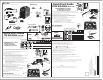
A) Fit the MIG Torch to the power source by pushing the MIG torch connector into the
MIG torch adaptor and screwing the plastic torch nut clockwise to secure the MIG torch to
the MIG torch adaptor.
MIG Gun Adaptor
(outside surface)
MIG Gun
Connector
Wire
Torch Nut
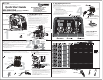
1. INSTALL Wire Spool
Wire Drive Tension Screw
Arm
Inlet Guide
Wire Drive Tension Screw
Pressure Roller Arm
Feed Wire
TILT
A) Drive Roll installed on machine is .030". If running other wire sizes and wire types
please see Operators Manual.
B) Install Spool
• Open side panel of 180i and mount the 8” diameter Wire Spool on Spool Hub.
Ensure Wire Spool seats onto Spool Hub Pin. (See Operator’s Manual for
alternate 8“ and 4” diameter spool set up.)
• Hand feed the wire from the spool into the Inlet Guide. (Wire is under tension.)
• Tilt the Wire Drive Tension Screw Arm toward the front of the machine and
feed the wire through the Outlet Guide about 3”.
• Return the Wire Drive Tension Screw Arm to the upright position locking the
Pressure Roller Arm underneath it. Ensure wire is seating in drive roll groove.
• Turn Wire Drive Tension Screw clockwise until drive roll grips wire.
Drive Roll and Drive Roll Knob
Drive Roll
Feed Wire
System
{
Outlet Guide
TRIGGER
WIRE
MIG GUN
TRIM
Gas Outlet
A) Attach the regulator to the cylinder valve and tighten securely with a wrench.
B) Purge the regulator by SLIGHTLY opening the cylinder valve for 3-to-5 seconds
and then close.
C) Connect the 180i gas hose to the gas outlet on the regulator. Wrench tight 1/4 turn.
D) Slowly and carefully open the cylinder valve until the maximum pressure
shows on the High-Pressure gauge.
E) Adjust regulator knob on the Low-Pressure gauge so the needle is
in the MIG, (Green Section).
2. SETUP Gas Regulator
Cylinder Valve
Regulator
High-PressureLow-Pressure
Tighten with
wrench
Regulator
Adjusting
Knob
Clamp to work piece
before starting to weld.
Work Clamp
Work Clamp
Connector
G
MIG Gun Connector
B) Plug the 180i into a 208-265V outlet.
3. SETUP MIG Gun
C) Turn the Power Switch ON. (Located on the rear of the machine.)
D) Select MIG PROCESS.
E) Select 2T for TRIGGER.
F) Turn WIRESPEED Dial to Five. (Halfway between 4 and 6 marks)
G) Switch the LOCAL/REMOTE switch inside the wire feed
compartment to LOCAL.
Then switch the MIG GUN/SPOOL GUN switch to MIG GUN.
H) Lay the MIG Gun out so the cable is straight with NO twists or kinks.
• Unscrew nozzle and pop out the tip from MIG gun.
• Point the MIG Gun AWAY from your body. Press and hold the
MIG Gun trigger. The wire will advance through the cable and
out the MIG Gun conductor tube. Release the MIG Gun trigger.
• Reinstall MIG Gun tip and nozzle.
• Trim the wire at the MIG Gun nozzle to desired stick out.
• Close the 180i side panel.
A) Select MIG PROCESS.
B) Determine what material type and thickness you plan to weld (24 ga. through 1/16” thickness).
C) Determine what wire type and diameter you plan to use (.030”recommended).
D) Determine what shielding gas you plan to use (75% Ar/25% CO
2
recommended).
E) Quick Start Parameters:
for 16 gauge (1.6 mm)
1) Wirespeed Display: 300
2) Voltage Display: 16.5 (16.5V)
3) Inductance Setting: 10 (+HARD)
Otherwise, refer to your ‘Recommended Settings Chart’ below for
Wirespeed, Voltage, and Inductance Settings.
F) Attach Work Clamp connector to 180i.
Check for Positive polarity setting — see picture.
G) Attach Work Clamp to work piece.
4. SET Welding Parameters
OPTIONAL: Installing or Replacing Nozzle or Tip
1.) Unplug the 180i.
2.) Unscrew worn nozzle and pop out the tip.
3.) Slide new contact tip into the conductor tube end.
(Tip does not screw in.)
4.) Replace the nozzle. Hand tighten (Nozzle secures tip).
NOTE: For proper operation the nozzle MUST be tight.
5.) Trim wire to desired stick out.
NOZZLE
TIP
TRIGGER
MIG GUN
*Recommended
Quick Start
Parameters
You may begin welding.
180i Shut Down
A) Turn the Power Switch OFF.
(Located on the rear of the machine.)
B) Turn cylinder valve OFF and
bleed downstream gas line by loosening
hose at back of 180i.
When nished welding, remember to
properly shut down the 180i.
Spool Hub
Pin hole
Side Panel
Recommended Settings Chart
(For your reference this chart is also on the inside side panel.)
.030
0.8
.030” (0.8 mm) Stamp
Tack Weld
MIG Gun
MIG WELDING Step outline:
1) INSTALL Wire spool
2) SETUP Gas Regulator
3) SETUP MIG Gun
4) SET Welding Parameters
Quick Start Guide
MIG WELDING (0.030” Solid Wire)
MST 180i
Publication Date: July 29, 2015Revision: ABQuick Start Guide Number: 0-5337
3-IN-1 Multi Process Welding Systems