IT EN FR DE ES Istruzioni per installazione Installation manual Instructions pour l’installation Installationsanweisung Instrucciones para instalación EW2 SERIES INDUSTRIAL PANEL PC
1 E W 2 1 2 A 2 E W 2 1 2 B 3 E W 2 1 2
4 E W 2 1 5 A 5 E W 2 1 5 B 6 E W 2 1 5
7 E W 2 1 8 A 8 E W 2 1 8 B 9 E W 2 1 8
1 0 E W 2 2 2 A 1 1 E W 2 2 2 B 1 2 E W 2 2 2
1 3 E W 2 . . A 1 4 1 2 FRONT BACK 1 E W 2 . .
1 6 A E E W 2 B 1 7 E W 2 F 1 8 E W 2 CFAST PUSH PUSH HDD/SSD PUSH PULL C D
1 9 E W 2 2 0 E W 2 2 1 E W 2
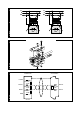
2 2 E W 2 2 3 Power supply 4 pins connectors 1 +24 VDC 2 0 VDC 3 Not Connected 4 Protective ground E W 2 2 4 L1 N PE ~ - 24V + DEVICE PE +24V 0V EW2xx E W 2 1 2 3 4
2 5 L1 N PE L1 N PE ~ - E W 2 24V ~ + - 24V + 2 6 E W 2 2 7 CONNECTOR D-SUB 9 PIN FEMALE +5VDC 470 ohm 1/4 W DATA+ 220 ohm 1/4 W DATA- 1 DATA+ 120 ohm 1/4 W 2 DATA- 470 ohm 1/4 W GND E W 2 DEVICE EW2
2 8 D-SUB 9 PIN FEMALE CONNECTOR +5VDC 470 ohm 1/4 W DATA+ 220 ohm 1/4 W DATA470 ohm 1/4 W GND E W 2 DEVICE 6,8V 600W 1 DATA+ 120 ohm 1/4 W 2 DATA6,8V 600W 5 GND EW2
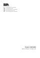
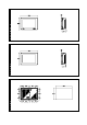
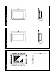
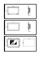
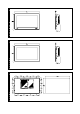
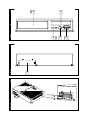
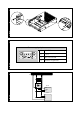
IT_Italiano AVVERTENZA IMPORTANTE: leggere attentamente queste istruzioni prima della installazione del prodotto. Dimensioni e forature EW212A – Fig. 1 . 3 EW212B – Fig. 2 . 3 EW215A – Fig. 4 . 6 EW215B – Fig. 5 . 6 EW218A – Fig. 7 . 9 EW218B – Fig. 8 . 9 EW222A – Fig. 10 . 12 EW222B – Fig. 11 . 12 Vista frontale EW2xxA – Fig. 13 1) Porta seriale USB. 2) Power led. Vista posteriore EW2 – Fig. 16 . 17 A) Vedi manuale scheda madre. B) COM - Vedi manuale scheda madre.
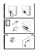
ATTENZIONE: la piastrina di chiusura DEVE essere montata PRIMA dell’installazione in ambiente ATEX. Attenersi alle indicazioni riportate in Fig. 14. 1. Rimuovere la guarnizione dal supporto di protezione 2. Applicare la guarnizione sulla parte posteriore della piastrina di chiusura USB. 3. Aprire completamente il tappo di gomma e applicare con le apposite viti la piastrina di chiusura USB. 4. Richiudere il tappo di gomma. Installazione EW2 EW2 – Fig.
ATTENZIONE: queste due configurazioni danneggiano gravemente il EW2 - Fig. 25. IMPORTANTE: La massa dei dispositivi collegati alle porte di comunicazione seriali e/o parallele deve essere tassativamente allo stesso potenziale dello 0V di alimentazione del EW2. La circolazione di una corrente tra lo 0V di alimentazione e la massa delle porte di comunicazione potrebbe causare il danneggiamento di alcuni componenti del EW2 o dei dispositivi ad esso collegati.
EN_English WARNING IMPORTANT: Please read carefully these instructions before mounting the product. Dimensions and holes EW212A – Fig. 1 . 3 EW212B – Fig. 2 . 3 EW215A – Fig. 4 . 6 EW215B – Fig. 5 . 6 EW218A – Fig. 7 . 9 EW218B – Fig. 8 . 9 EW222A – Fig. 10 . 12 EW222B – Fig. 11 . 12 Front view EW2xxA – Fig. 13 1) Universal Serial Bus port. 2) Power led. Rear view EW2 – Fig. 16 . 17 A) See motherboard manual. B) COM - See motherboard manual. C) POWER (ATX power on switch) See motherboard manual.
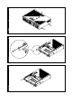
1. Remove the gasket from protective support. 2. Apply the gasket on the rear side of the closing plate for the USB port. 3. Open completely the rubber USB cover, insert the closing plate in the USB hole and fix the plate by using the proper screws. 4. Close the rubber USB cover Installing the EW2 EW2 – Fig. 15 Inserting/Removing HDD/SSD/CFast Please follow the instructions by Fig. 18. a. Switch off EW2xx. b. Unscrew the threaded knob and remove the closing plate.
components of the EW2 or of the devices connected to it. Working temperature 0 / +50°C Electromagnetic compatibility Restriction of use: protection requirements are not ensured in residential areas. Communication ports Refer to motherboard documentation for connection of link to peripheral devices. Cleaning For cleaning the EW2 we recommend Denaturalised Ethyl Alcohol.
FR_Français AVERTISSEMENT IMPORTANT : lire attentivement ces instructions avant l’installation du produit. Dimensions et perçage EW212A – Figure . 1 . 3 EW212B – Figure . 2 . 3 EW215A – Figure . 4 . 6 EW215B – Figure . 5 . 6 EW218A – Figure . 7 . 9 EW218B – Figure . 8 . 9 EW222A – Figure . 10 . 12 EW222B – Figure . 11 . 12 Vue frontale EW2xxA – Figure . 13 1) Port Universal Serial Bus. 2) Power led. Vue postérieure EW2 – Fig. 16 .
ATTENTION : le couvercle de fermeture doit être monté avant l’installation dans un environnement ATEX Suivre les indications données sur la Figure . 14. 1. Retirer le joint du support de protection 2. Appliquer le joint sur la partie postérieure du couvercle de la porte USB. 3. Ouvrir complètement le bouchon en caoutchouc et fixer avec les vis le couvercle de la porte USB. 4. Remettre en place le bouchon en caoutchouc. La dimension maximum autorisée est 180mm. a. Éteindre le EW2. b.
IMPORTANT : La masse des dispositifs connectés aux ports de communication parallèles ou sériels doit formellement être au même potentiel qu’il 0V d’alimentation du EW2. La circulation d’un courant entre il 0V d’alimentation et la masse des ports de communication pouvait causer des dommages aux composants du EW2 ou des dispositifs connectés. Température d’exercice 0 / +50°C Compatibilité électromagnétique Restriction d'emploi: les protection n'est pas assurée dans les zones résidentielles.
! DE_Deutsch HINWEIS WICHTIG: lesen Sie die Hinweise sorgfältig durch bevor Sie Installationen durchführen. Maße und Ausschnitt EW212A – Abbildung . 1 . 3 EW212B – Abbildung . 2 . 3 EW215A – Abbildung . 4 . 6 EW215B – Abbildung . 5 . 6 EW218A – Abbildung . 7 . 9 EW218B – Abbildung . 8 . 9 EW222A – Abbildung . 10 . 12 EW222B – Abbildung . 11 . 12 Vorderansicht EW2xxA – Abbildung . 13 1) Universelles serielles Busanschluß. 2) Power LED. Rückansicht EW2 – Abbildung . 16 .
Installation in explosionsgefährdete Umgebung Um die EW2xxA Familie in eine explosionsgefährdete Umgebung zu verwenden, muß der spezielle, mit dem Produkt gelieferte Installationssatz, eingesetzt werden. Details siehe separate Installationsanleitung. ACHTUNG: Die Abdeckung muss vor dem Einbau in eine explosionsgefährdete Umgebung wieder aufgesetzt werden. Folgen Sie den Anweisungen aus Abbildung . 14. 1. Entfernen Sie die Dichtung. 2. Befestigen Sie die Dichtung auf der Rückseite der USB Deckplatte. 3.
ACHTUNG: Bei Batteriewechsel auf korrekte Polung achten. Altbatterien müssen entsprechend entsorgt werden. d. Das Gehäuse wieder aufsetzen. Spannungsversorgung Reinigung Oberfläche der Touch- Für die Reinigung der Touch Oberfläche wird die Verwendung von Ethylalkohol empfohlen. Zertifizierungen Anschluß des Versorgungssteckers - siehe Abbildung . 23. Empfohlene Verdrahtung - suehe Abbildung . 24. WARNUNG: Diese beiden Anschlussarten führen zu Schäden am EW2 Gerät - siehe Abbildung . 25.
ES_Español ADVERTENCIA IMPORTANTE: leer estas instrucciones con cuidado antes de la instalación producto. Dimensiones y perforaciones EW212A – Fig. 1 . 3 EW212B – Fig. 2 . 3 EW215A – Fig. 4 . 6 EW215B – Fig. 5 . 6 EW218A – Fig. 7 . 9 EW218B – Fig. 8 . 9 EW222A – Fig. 10 . 12 EW222B – Fig. 11 . 12 Vista frontal ! Apantallado > 80% o tota En todo caso: ! Busque el recorrido más corto. ! No realice el tendido junto a cables con perturbaciones.
las instrucciones que se incluyen con el producto. Inserción de una tarjeta PCI o bien PCIe ATENCIÓN: La tapa de cierre debe instalarse antes de la instalación en zona ATEX. EW2 preve el alojamiento de una tarjeta PCI o bien PCIe. El tamaño máximo permitido es 180mm. Siga las instrucciones indicadas en la Fig. 14. 1. Retire la junta del soporte protector. 2. Coloque la junta en la parte posterior de la tapa USB. 3.
ATENCION: Las dos configuraciones de arriba dañan gravemente el EW2 - Fig. 25. ATENCION: La masa de los dispositivos conectados en los puertos de comunicación serie y/o paralelo tiene que estar conectada imprescindiblemente al mismo potencial del 0V de alimentación del EW2. La circulación de una corriente entre el 0V de alimentación y la masa de los puertos de comunicación podría causar daños a algunos componentes del EW2 o bien a algunos dispositivos conectados.
ESA elettronica S.p.A. Via Padre Masciadri, 4/A 22066 Mariano Comense (CO) ITALY Tel. ++39.031757400 Fax ++39.031751777 Web: www.esaware.com E-mail: customer.care@esahmi.com Rev. 0 Date: 17/07/2014 405.1300.216.