
Specifications

VCES-ERV-IOM-3B – Indoor ERV
9
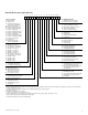
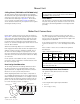
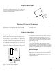
Handles for access panels are provided but must be in-
stalled on site. Handles and fasteners are secured on the
top of the unit. Remove from packaging and install ac-
cording to the drawing below.
Remove access panels and all packaging from the unit.
Note that there is packaging for wheel support during
shipping (ERV1000i and ERV2000i). Removal of all this
packaging is critical.
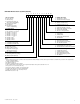
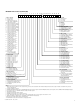
Forced Air System
When the ERV is installed in conjunction with a forced
air system, the air handler and the network of ducts as-
sociated with it are used to distribute fresh air inside the
building. If this type of system is used, the main fan of the
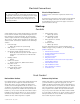
air handler must operate continuously when the unit is on.
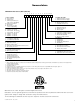
Fan interlock can be connected in the unit control box to
the integrated control board terminals J3-1 and J3-2 (for
low voltage Class II circuit only). The controller makes relay
contact between these terminals when the unit is operat-
ing, as shown in Figure 3.
Fresh air from the ERV should be introduced into the re-
turn duct of the air handler at a point no less than 6 feet
[1,829 mm] upstream of the air handler. The duct con-
nection for return air to the ERV should be made on the
return air duct at least 2 feet [610 mm] upstream of the
fresh air duct connection.
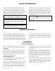
Separate Systems
Select locations for exhaust grilles and supply diffusers
to provide effective ventilation and avoid short circuiting
airflows through the space. Adjustable dampers should be
provided at every grille and diffuser to make balancing of
the system possible.
Backdraft Damper
A backdraft gravity damper is supplied with recirculation
defrost units to be installed in the exhaust air outlet duct.
This damper is necessary to prevent air from entering the
building through the exhaust duct when the unit is in re-
circulation defrost mode.
Install Access Panels
Remove All Internal Packaging
Systems Integration
Metal or
polyamide
handle
#10 x ¾ Screw
Access panel
Figure 2: Access panel
132
J1
6
9
4
7
G
1
J2
COMM.
N/C
N/O
J3
21
FF
J4
JU1
3
I
OC
OL
R
48644 power
control board
YB
A B C D E F G
Fan interlock
contacts
+++++++
+++++++
JU1G – Intermittent standy (IS)
JU1F – Extended defrost
Figure 3: Forced air system integration