
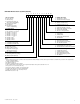
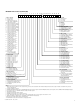
Specifications

VCES-ERV-IOM-3B – Indoor ERV
8
Ceiling Mount (ERV1000i and ERV2000i only)
The unit must be mounted level and may be hung with
threaded rod (field supplied) through the protruding frame
at the base of the unit. Hole centers are shown in the
overall dimension drawings in Appendix C. Do not block
access to panels as indicated in Appendix B. Rubber or
seismic vibration isolation may be required in some regions
(field supplied and specified).
Floor Mount
The unit may be secured to the floor using isolation/vibra-
tion pads. The pads may be located on each corner of the
unit’s frame (all mounting hardware is field supplied and
specified).
Port locations, labels and sizes for the units are shown in
Appendix C. Transitions (field supplied) may be required to
make connection with ductwork that is properly sized for
minimum noise and pressure loss. Both duct connections
to outside must be insulated to avoid condensation and
heat loss. A continuous integral vapor barrier must be used
over the duct insulation.
Airflow rate balancing dampers are recommended for
both supply and exhaust ducts to allow for adjustment of
airflows. Flexible connectors should be installed close to
the unit in the duct leading to occupied spaces to mini-
mize noise transmission. Ensure that the fasteners used to
make duct connection do not interfere with fans or damp-
ers in the unit.
Electric preheat in the outdoor air duct, if used as frost
prevention, must be installed at a minimum distance from
the unit of 24” [610 mm].
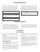
Duct Design Considerations
The discharge ductwork immediately downstream from
the fan is critical for successful applications. Poorly de-
signed ductwork can degrade fan performance and con-
tributes to excessive pressure drop and noise.
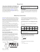
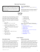
When designing ductwork in the field, it is important to
use a straight discharge duct of the correct dimensions to
obtain maximum fan performance. The straight section of
ductwork helps the airflow to develop a uniform velocity
profile as it exits the fan and allows the velocity pressure
to recover into static pressure. See Figure 1.
For 100% recovery of velocity pressure into static pres-
sure, the straight portion of the discharge duct must be at
least 2.5 times the discharge diameter to the length of the
straight portion of ductwork.
As an example of how to size the straight portion of duct,
assume the fan has a 13.5” x 9.5” discharge outlet = 0.89
ft
2
.
Refer to Table 1 for the effect of undersized equivalent
duct diameter.
Calculate Equivalent Duct Diameter
The equivalent duct diameter of the fan outlet:
= (4ab ÷ π)
0.5
= (4 x 13.5 x 9.5)
0.5
π
= 12.75
= ~13
So the straight duct length required would be:
= 2.5 x 13
= 32.5” long [2.7 feet]
Mount Unit
Make Duct Connections
Centrifugal fan
Cutoff
Discharge duct
100% effective duct length
2½ diameters at 2,500 FPM
Figure 1: Duct design
IMPORTANT
The manufacturer recommends that the ERV1500i and
ERV3000i be floor mount only.
IMPORTANT
This information is referenced from AMCA Fans and Sys-
tems Publication 201-90.
Table 1: Duct Design Effectiveness
No
Duct
12%
Effective
Duct
25%
Effective
Duct
50%
Effective
Duct
100%
Effective
Duct
Pressure
recovery
0% 50% 80% 90% 100%