
Specifications
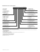
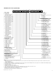

VCES-ERV-IOM-3B – Indoor ERV
7
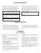
Safety Considerations
General Information
Installation
Check Equipment
Warning, Caution and Important notes appear through-
out this manual in specific and appropriate locations to
alert Installing Contractors and maintenance or service
personnel of potential safety hazards, possible equipment
damage or to alert personnel of special procedures or in-
structions that must be followed as outlined below.
Hazards may exist within this equipment because it con-
tains electrical and powerful moving components. Only
qualified service personnel should install or service this
equipment. Untrained personnel can perform basic main-
tenance such as maintaining filters. Observe precautions
marked in literature and on labels attached to the unit.
Follow all safety codes.
The indoor Energy Recovery Ventilators (ERVs) are in-
tended for installation within a suspended ceiling space or
mechanical room. These ventilators provide 100% outside
air ventilation as well as energy recovery between the ex-
haust and supply airstreams. The Energy Recovery Ventila-
tors (ERVs) use an enthalpy wheel for total energy recovery
providing superior efficiency in hot and humid climates.
These models are also effective in cold climates and use
various types of frost control or frost prevention to ensure
operation when the outside temperatures are extremely
low.
Move the unit to its installation location and remove pack-
aging. See Appendix A for unit weight and specifications.
Inspection
Inspect the equipment, exterior and interior, for damage.
Ensure that there is no damage to the internal compo-
nents such as fans, motors, dampers, enthalpy wheel,
insulation and structures. File a claim with the shipping
company if the unit is damaged.
System Requirements
Consult local building codes and National Electrical Code
for special installation requirements. See Appendix H for
more electrical data information.
The unit should be installed to allow easy access for main-
tenance. See Appendix B for minimum clearance required
between front access and any obstruction to allow for
removal of components (fans, filters, enthalpy wheel). The
front of the unit is defined in relation to the inlet ports
and outlet ports on the unit. See Appendix C for port loca-
tion and overall dimensions. Unit components are shown
in Appendix D.
In cold climates with −5°F [−20°C] design, the unit must
be mounted in a dry area (not exceeding 30% RH) to
avoid water condensation on the cabinet during winter
operation. Alternatively, accommodation must be made
for condensation on the cabinet exterior. Do not mount
units in an area where exposure to electrical panels or
other hazards will occur.
A mounting location close to an exterior partition will min-
imize the length of insulated ductwork required. Appendix
B illustrates ductwork through exterior partitions. These
should be separated by a minimum of 8 feet [2,438 mm]
to avoid outside cross contamination.
CAUTION
Identifies an instruction which, if not followed, might se-
verely damage the unit, its components, the assembly or
final installation.
IMPORTANT
Indicates supplementary information needed to fully
complete an instruction or installation.
WARNING
Identifies an instruction which, if not followed, might cause
serious personal injuries including possibility of death.
!
WARNING
Disconnect the main power switch to the unit before per-
forming service or maintenance. Electric shock can cause
personal injury.
!