
Specifications

VCES-ERV-IOM-3B – Indoor ERV
27
CO
2
Ventilation Control
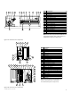
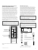
ERVs can be controlled by a CO
2
controller that can be
connected to fan control Low-Com-High (not all units
have two speeds). As the CO
2
levels exceed acceptable
limits, the dry contact across High-Com is closed, raising
high speed fan ventilation.
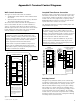
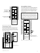
Unoccupied Recirc Contacts
On recirc defrost units, an unoccupied recirc control can
be achieved by connection to the terminal interface shown
below. These terminals require a 24 VAC signal which
could be provided by a timer, thermostat or other. Closure
of these terminals will cause the unit to go into a recirc
mode where the supply fan runs on high speed and the
exhaust fan stops.
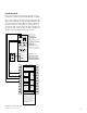
IMPORTANT
Although these contacts are intended for use during
unoccupied periods, they are still active during an occu-
pied condition. Therefore, the 24 VAC signal should be
applied such that it is disabled during occupied periods,
preventing the unit from going into a recirc condition un-
necessarily.
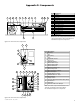
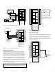
24 VAC LIGHT or INDICATOR
(supplied by others)
WRS BOARD RELAY
'NC' CONTACTS
(normally closed –
opens on wheel failure)
CONTROL CONTACTS
CLASS 2 VOLTAGE
WALL CONTROL
BLACK
1
2
3
4
5
6
7
8
9
10
11
12
13
14
15
16
17
18
19
20
NOTE:
Connections are all dry contacts
except wall control, wheel alarm
contacts and 24 VAC power contacts.
Use of 24 VAC circuit requires
isolating contacts (ex. thermostat)
to prevent interconnection of
Class 2 outputs.
RED
OCCUPIED
TIMER/
SENSOR
FIELD WIRED
TERMINALS
AB
UNOCC.
RECIRC
CONTACTS
LOW
COMMON
HIGH
DIRTY
FILTER
INDICATOR
(1.5A–24 VAC)
(ERV UNITS)
WHEEL
ALARM
OPTION
(24 VAC)
(ERV UNITS)
ENTHALPY
(−) 24 VAC
(40 VA)
(+) 24 VAC
GREEN
YELLOW
(RECIRC UNITS)
Figure E9: Wheel rotation alarm
FACTORY MOUNTED
JUMPER
CO
2
SENSOR
AC INPUT
AC GROUND
NC NO
CONTROL CONTACTS
CLASS 2 VOLTAGE
WALL CONTROL
BLACK
1
2
3
4
5
6
7
8
9
10
11
8
12
13
14
15
16
17
18
19
20
NOTE:
Connections are all dry contacts
except wall control, wheel alarm
contacts and 24 VAC power contacts.
Use of 24 VAC circuit requires
isolating contacts (ex. thermostat)
to prevent interconnection of
Class 2 outputs.
Note 1: Terminal 5 on CO
2
sensor
used only with two-speed units.
Note 2: Terminal 7 and 8 on CO
2
sensor used only with blower VFDs.
NORMAL OPERATION – LOW SPEED
CO
2
LEVELS EXCEED SETPOINT – HIGH SPEED
RED
OCCUPIED
TIMER/
SENSOR
FIELD WIRED
TERMINALS
AB
UNOCC.
RECIRC
CONTACTS
LOW
COMMON
HIGH
DIRTY
FILTER
INDICATOR
(1.5A–24 VAC)
(ERV UNITS)
WHEEL
ALARM
OPTION
(24 VAC)
(ERV UNITS)
ENTHALPY
(−) 24 VAC
(40 VA)
(+) 24 VAC
GREEN
YELLOW
(RECIRC UNITS)
7
6
5
3
2
1
2
1
4
Figure E10: CO
2
ventilation control
CONTROL CONTACTS
CLASS 2 VOLTAGE
WALL CONTROL
BLACK
1
2
3
4
5
6
7
8
9
10
11
12
13
14
15
16
17
18
19
20
NOTE:
Connections are all dry contacts
except wall control, wheel alarm
contacts and 24 VAC power contacts.
Use of 24 VAC circuit requires
isolating contacts (ex. thermostat)
to prevent interconnection of
Class 2 outputs.
RED
OCCUPIED
TIMER/
SENSOR
FIELD WIRED
TERMINALS
AB
UNOCC.
RECIRC
CONTACTS
LOW
COMMON
HIGH
DIRTY
FILTER
INDICATOR
(1.5A–24 VAC)
(ERV UNITS)
WHEEL
ALARM
OPTION
(24 VAC)
(ERV UNITS)
ENTHALPY
(−) 24 VAC
(40 VA)
(+) 24 VAC
GREEN
YELLOW
(RECIRC UNITS)
Note: Unoccupied recirculation
is available on units with
recirculation defrost option only.
24 VAC
required
Figure E11: Unoccupied recirc contacts