
Specifications

VCES-ERV-IOM-3B – Indoor ERV
26
Wheel Rotation Sensor used as Low Tem-
perature Control (Wheel Failure)
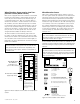
ERVs can be equipped with a wheel rotation sensor board
but must be ordered with a control board. On power up
of the unit, the wheel rotation sensor board’s relay coil
is activated and closes the ‘NO’ set of contacts that are
wired to the ‘Occ/Unocc’ control terminals on the unit. In
this condition, the unit is allowed to operate in a normal
occupied state. When a wheel rotation failure occurs, the
relay coil is de-activated and opens the contacts that are
wired to the ‘Occ/Unocc’ control terminals. In this condi-
tion, the unit is in an unoccupied state. The fans are de-
energized and the outdoor air dampers will close.
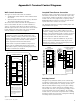
The wheel rotation sensor board has jumpers that can
be used to set the time duration (one, two, four or eight
minutes) for the alarm to be activated after the wheel fail-
ure. This alarm can be used to turn on an alarm light (see
Figure E9) or to protect downstream coils from freezing in
below zero conditions.
Wheel Rotation Sensor
ERVs can be equipped with a wheel rotation sensor op-
tion. This option cannot be ordered for a non-defrost unit.
This option cannot be used in conjunction with a digital
wall control and must be ordered with a control board.
With the wheel rotating, the wheel rotation sensor board
activates the relay coil and closes the ‘NO’ (normally open)
set of contacts across the occupied/timer sensor contacts
(Pin 3 and 4), allowing the unit to operate. If the wheel
rotation stops (unless in an enthalpy state, defrost mode
or unoccupied condition), the contacts will be open and
cause the motors to shut down and the dampers (op-
tional) to close.
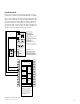
A set of 24 VAC wheel alarm contacts are available on the
terminals to power a light or indicator. The drawing below
shows the wiring necessary to power the 24 VAC light or
indicator.
IMPORTANT
The wheel rotation sensor option must be ordered with
a unit control board for wall control compatibility. The
wheel rotation sensor option cannot be ordered with a
non-defrost unit.
IMPORTANT
If the wheel rotation sensor board shuts the unit down,
the only procedure to re-start the unit is to turn the
power off and then back on again.
24 VAC LIGHT or INDICATOR
(supplied by others)
WRS BOARD RELAY
'NC' CONTACTS
(normally closed –
opens on wheel failure)
CONTROL CONTACTS
CLASS 2 VOLTAGE
WALL CONTROL
BLACK
1
2
3
4
5
6
7
8
9
10
11
12
13
14
15
16
17
18
19
20
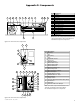
NOTE:
Connections are all dry contacts
except wall control, wheel alarm
contacts and 24 VAC power contacts.
Use of 24 VAC circuit requires
isolating contacts (ex. thermostat)
to prevent interconnection of
Class 2 outputs.
RED
OCCUPIED
TIMER/
SENSOR
FIELD WIRED
TERMINALS
AB
UNOCC.
RECIRC
CONTACTS
LOW
COMMON
HIGH
DIRTY
FILTER
INDICATOR
(1.5A–24 VAC)
(ERV UNITS)
WHEEL
ALARM
OPTION
(24 VAC)
(ERV UNITS)
ENTHALPY
(−) 24 VAC
(40 VA)
(+) 24 VAC
GREEN
YELLOW
(RECIRC UNITS)
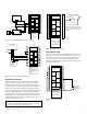
Figure E7: Wheel rotation sensor used as low temperature
control
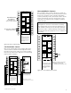
LED 1 2 3
NO COM NC 24V COM VENSEN ALA DIS
NO COM NC
24 COM SEN
DEF+ DEF−
CAUTION
120 VAC
DEF+ DEF-
CAUTION
120 VAC
VEN ALA DIS
NO = NORMALLY OPEN
NC = NORMALLY CLOSED
COM = COMMON
24V = 24 VAC
COM = COMMON
SEN = SENSOR
ALA = RELAY ON (24 VAC LIGHT, MAX. 1 AMP)
DIS = ROTATION DETECTOR DISABLE (24 VAC)
VEN = VENTILATION MODE (DISABLE WRS) (24 VAC)
DEF+ = DEFROST MODE (DISABLE WRS) (120 VAC)
DEF- = DEFROST MODE (DISABLE WRS) (120 VAC)
NO NC
RELAY
COM SEN
COM
SENSOR
MAGNET
J1 J2
DELAY
J1 J2
DELAY
LED 1 2 3
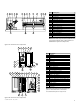
J1 & J2 = DETECTION DELAY
J1 J2 DELAY
1 min.
X 2 min.
X 4 min.
X X 8 min.
*default
1 = RELAY ON (RED)
2 = POWER ON (GREEN)
3 = SENSOR DETECTION INDICATOR (YELLOW)
*
Figure E8: Wheel rotation sensor board
CAUTION
The wheel rotation sensor printed circuit board has 120
VAC wired to two terminals. Improper wiring or handling
of the circuit board could damage the board, the unit or
cause personal injury.