
Specifications

VCES-ERV-IOM-3B – Indoor ERV
25
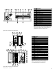
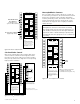
Remote Fan Control
Remote fan control can be achieved by connecting dry
contact controls to the terminal interface at terminals
labeled: Low-Com-High (not all units have two speeds).
Placing a jumper across the ‘Low’ and ‘Com’ terminals will
put the unit in low speed ventilation or placing a jumper
across the ‘High’ and ‘Com’ terminals will put the unit into
high speed. Do not jumper all three terminals together.
These controls could also be the following: SPDT switch,
dehumidistat, CO
2
sensor, light sensor, heat sensor, timer,
Building Management System, etc. Figure E5represents a
switch connected to the unit.
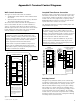
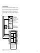
Dirty Filter Sensor
The ERVs can be equipped with dirty filter sensors which
monitor the pressure across the filters and close the con-
tacts when the filters become restricted with dirt. Con-
nections on the terminal interface labeled ‘Dirty Filter
Indicator’ provide the dry contact and may be connected
as shown in Figure E6.
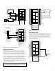
THERMOSTAT
(FIELD SUPPLIED)
TO AC UNIT
COIL (24 VAC)
TO AC UNIT
COIL (GND)
+
−
+
−
GND
24 VAC
LOW HI
Y R C
A/ENT
SENSOR
MOUNTED IN
RETURN AIRSTREAM
A/DIFF-ENT ENTHALPY CONTROL
MOUNTED IN OUTDOOR AIRSTREAM
1
2
3
4
5
6
7
8
9
10
11
12
13
14
15
16
17
18
19
20
CONTROL CONTACTS
BLACK GREEN
WALL CONTROL
RED YELLOW
A FIELD WIRED B
TERMNIALS
OCCUPIED
TIMER/
SENSOR
LOW
COMMON
HIGH
DIRTY
FILTER
INDICATOR
(1.5A–24 VAC)
(RECIRC UNITS )
UNOCC.
RECIRC
CONTACTS
(ERV UNITS)
ENTHALPY
(ERV UNITS)
WHEEL
ALARM
OPTION
(24 VAC)
(−) 24 VAC
(40 VA)
(+) 24 VAC
CLASS 2 VOLTAGE
NOTE:
Connections are all dry contacts
except wall control, wheel alarm
contacts and 24 VAC power
contacts.
Use of 24 VAC circuit requires
isolating contacts
(ex. thermostat) to prevent
interconnection of Class 2
outputs.
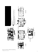
Setpoint PN 500053119S (A/Diff-ENT)
Differential PN 500053120S (A/Ent)
Figure E3: Setpoint/differential enthalpy control
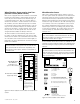
THERMOSTAT
(FIELD SUPPLIED)
Y R C
B R W
NO CM NC
TO AC UNIT
COIL (24 VAC)
TO AC UNIT
COIL (GND)
JUMPER
T675A TEMP.
CONTROLLER
1
2
3
4
5
6
7
8
9
10
11
12
13
14
15
16
17
18
19
20
CONTROL CONTACTS
BLACK GREEN
WALL CONTROL
RED YELLOW
A FIELD WIRED B
TERMNIALS
OCCUPIED
TIMER/
SENSOR
LOW
COMMON
HIGH
DIRTY
FILTER
INDICATOR
(1.5A–24 VAC)
(RECIRC UNITS )
UNOCC.
RECIRC
CONTACTS
(ERV UNITS)
ENTHALPY
(ERV UNITS)
WHEEL
ALARM
OPTION
(24 VAC)
(−) 24 VAC
(40 VA)
(+) 24 VAC
CLASS 2 VOLTAGE
NOTE:
Connections are all dry
contacts except wall control,
wheel alarm contacts and
24 VAC power contacts.
Use of 24 VAC circuit requires
isolating contacts
(ex. thermostat) to prevent
interconnection of
Class 2 outputs.
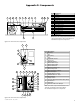
Setpoint PN 1604130 (T675A)
Figure E4: Thermostat (dry bulb) control
REMOTE FAN SWITCH
LOW
HIGH
CONTROL CONTACTS
CLASS 2 VOLTAGE
WALL CONTROL
BLACK
1
2
3
4
5
6
7
8
9
10
11
12
13
14
15
16
17
18
19
20
NOTE:
Connections are all dry contacts
except wall control, wheel alarm
contacts and 24 VAC power contacts.
Use of 24 VAC circuit requires
isolating contacts (ex. thermostat)
to prevent interconnection of
Class 2 outputs.
RED
OCCUPIED
TIMER/
SENSOR
FIELD WIRED
TERMINALS
AB
UNOCC.
RECIRC
CONTACTS
LOW
COMMON
HIGH
DIRTY
FILTER
INDICATOR
(1.5A–24 VAC)
(ERV UNITS)
WHEEL
ALARM
OPTION
(24 VAC)
(ERV UNITS)
ENTHALPY
(−) 24 VAC
(40 VA)
(+) 24 VAC
GREEN
YELLOW
(RECIRC UNITS)
Note: Not all units have two speeds.
Single speed units will be activated
with either Low-Com or High-Com
connection.
JUMPER
Figure E5: Remote fan control
24 VAC LIGHT
or INDICATOR
(supplied by others)
JUMPER
CONTROL CONTACTS
CLASS 2 VOLTAGE
WALL CONTROL
BLACK
1
2
3
4
5
6
7
8
9
10
11
12
13
14
15
16
17
18
19
20
NOTE:
Connections are all dry contacts
except wall control, wheel alarm
contacts and 24 VAC power contacts.
Use of 24 VAC circuit requires
isolating contacts (ex. thermostat)
to prevent interconnection of
Class 2 outputs.
RED
OCCUPIED
TIMER/
SENSOR
FIELD WIRED
TERMINALS
AB
UNOCC.
RECIRC
CONTACTS
LOW
COMMON
HIGH
DIRTY
FILTER
INDICATOR
(1.5A–24 VAC)
(ERV UNITS)
WHEEL
ALARM
OPTION
(24 VAC)
(ERV UNITS)
ENTHALPY
(−) 24 VAC
(40 VA)
(+) 24 VAC
GREEN
YELLOW
(RECIRC UNITS)
Figure E6: Dirty filter sensor
CAUTION
Do not use a wall control and remote fan switch at the
same time. Damage to the unit may occur.