
Specifications

VCES-ERV-IOM-3B – Indoor ERV
21
11.415”
[290]
28.000”
[711]
5.667”
[144]
6.166”
[157]
16.000”
[406]
13.321”
[338]
7.392”
[188]
6.965”
[177]
11.415”
[290]
7.806”
[198]
13.250”
[337]
14.000”
[356]
4.901”
[124]
29.000”
[737]
29.000”
[737]
OA-S
7.226”
[184]
86.578”
[2,199]
14.000”
[356]
89.008”
[2,261]
11.500”
[292]
3.625” [92] typical
bottom flange
7.040”
[179]
7.658”
[195]
13.250”
[337]
16.000”
[406]
5.877”
[149]
5.744”
[146]
28.000”
[711]
SA-B
55.226”
[1,403]
11.375”
[289]
13.250”
[337]
18.882”
[480]
7.807”
[198]
16.000”
[406]
49.878”
[1,267]
4.769”
[121]
9.072”
[230]
28.000”
[711]
4.865”
[124]
13.250”
[337]
10.093”
[256]
11.375”
[289]
24.671”
[627]
EA-S
17.349”
[441]
48.778”
[1,239]
SA-E
RA-E
18.777”
[477]
17.582”
[447]
24.773”
[629]
11.375”
[289]
EA-E
OA-E
26.500”
[673]
1.918”
[49]
3.042”
[77]
15.625”
[397]
13.321”
[338]
8.590”
[218]
4.680”
[119]
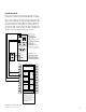
X
Y
D
B
A
C
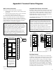
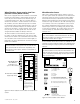
Control box
OA-T
RA-T
SA-T
Coil
mount
location
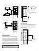
TOP VIEW
FRONT VIEW
BOTTOM VIEW
RIGHT VIEW
BACK VIEW
Exhaust
blower
access
panel
Cassette
and filter
access
panel
Coil
section
access
panel
Supply
blower
access
panel
Power
line input
Control
box
access
Filter
access
(minimum
clearance
24.000” [610])
LEFT VIEW
Coil stub location for
external connections
located in this section
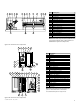
Variable Corner Weight Values ERV3000i
Corner weight value
No coils
With Dx only
With chilled H
2
O
With hydronic
With steam
Dx and hydronic
Dx and steam
Chilled and hydronic
Chilled and steam
A
BC
D
Y
X
Total Weights
LBS
266
246
246
248
250
237
239
237
239
LBS
215
222
222
221
221
220
220
220
220
KG
120.7
111.6
111.6
112.5
113.4
107.5
108.4
107.5
108.4
KG
97.5
100.7
100.7
100.2
100.2
99.8
99.8
99.8
99.8
LBS
275
269
269
269
269
271
270
271
270
KG
124.7
122.0
122.0
122.0
122.0
122.9
122.5
122.9
122.5
LBS
223
243
243
241
239
251
249
251
249
KG
101.2
110.2
110.2
109.3
108.4
113.9
112.9
113.9
112.9
LBS
979
1,057
1,054
1,052
1,036
1,130
1,114
1,12
7
1,111
KG
444.1
479.4
478.1
477.2
469.9
512.6
505.3
511.2
503.9
IN
24.5
23.8
23.8
23.9
24.0
23.3
23.4
23.3
23.4
MM
622
605
605
607
610
592
594
592
594
IN
47.9
46.5
46.5
46.7
46.9
45.9
46.0
45.9
46.0
MM
1,217
1,181
1,181
1,186
1,191
1,166
1,168
1,166
1,168
Variable Dim. Values
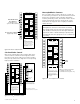
Notes:
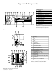
Dimensions in [ ] are millimeters.
Center of gravity
Optional
Note: On vertical discharge units, ductwork is to be attached to accessory roofcurb only.
On horizontal discharge units, field supplied flanges are to be attached to horizontal discharge
openings and ductwork is to be attached to the flanges.
Note: A minimum of 48.000” [1,219] clearance from any obstruction is required for removal of
energy recovery module, fans and filters.
RA-B
EA-T
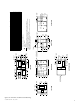
Figure C4: ERV3000i unit dimensional drawing