
Specifications

VCES-ERV-IOM-3B – Indoor ERV
20
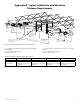
Exhaust air
to outside
Supply air
to building
Supply fan
control box
access panel
Supply air
opening
Exhaust
air opening
10.000”
[254]
5.380”
[137]
4.000”
[102]
2.000”
[51]
Field power supply
10.750”
[273]
48.000”
[1,219]
7.625”
[194]
7.625”
[194]
10.000”
[254]
5.250”[133]
12.750”
[324]
13.251”
[337]
14.000”
[356]
14.000”
[356]
36.500”
[927]
48.500”
[1232]
44.625”
[1,133]
23.000”
[584]
44.375”
[1,127]
46.000”
[1,168]
48.500”
[1,232]
12.000”
[305]
30.000”
[762]
12.000”
[305]
1.000”
[25]
26.000”
[660]
2.845”
[72]
3.500”
[89]
26.000”
[660]
1.750”
[44]
2.750”
[70]
91.000”
[2,311]
88.500”
[2,248]
85.000”
[2,159]
Outdoor air
opening
Return air
opening
Cassette, filter
access panel
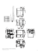
A minimum of 48.000” [1,219] clearance from any obstruction is required
for removal of energy recovery module, fans and filters.
Energy recovery
module
Return air
Filter
access panel
Exhaust fan
access panel
Outdoor air
C
A
B
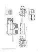
TOP VIEW
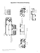
FRONT VIEWLEFT VIEW RIGHT VIEW
RIGHT VIEW
Low voltage connection
(leave 16.000” [406] in front for access)
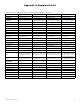
PTS
A
B
C
D
Total
LBS
173.73
158.22
192.62
175.43
700.00
Kg
78.80
71.76
87.37
79.57
317.52
ERV2000i
Notes:
Dimensions in [ ] are millimeters.
Center of gravity
Direction of airflow
Optional externally
mounted supply damper
for all Frost Control options
excluding ‘D – Recirc Defrost’
Hanging mount hole Ø 0.625” [16]
Note: If the unit is to be hung, materials
required to hang the unit will be
supplied by others.
D
Figure C3: ERV2000i unit dimensional drawing