
Specifications

VCES-ERV-IOM-3B – Indoor ERV
19
3.425”
[87]
7.450”
[189]
9.440”
[240]
21.500”
[546]
26.000”
[660]
43.190”
[1,097]
9.190”
[233]
10.250”
[260]
14.187”
[360]
8.068”
[205]
44.290”
[1,125]
3.165”
[80]
26.669”
[677]
15.500”
[394]
14.000”
[356]
53.347”
[1,355]
16.797”
[427]
9.190”
[233]
10.250”
[260]
43.556”
[1,106]
13.666”
[347]
9.029”
[229]
8.103”
[206]
10.763”
[273]
18.000”
[457]
50.094”
[1,272]
9.193”
[234]
8.842”
[225]
14.226”
[361]
10.250”
[260]
12.000”
[305]
55.754”
[1,416]
10.250”
[260]
7.028”
[179]
8.993”
[288]
9.25”
[235]
12.000”
[305]
8.502”
[216]
5.306”
[135]
16.000”
[406]
10.500”
[267]
2.319”
[59]
8.915”
[226]
9.440”
[240]
16.000”
[406]
3.775”
[96]
8.631”
[219]
13.500”
[343]
10.500”
[267]
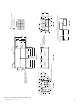
Control box
RA-T
EA-T
A
B
D
C
OA-E
RA-B
EA-E
Exhaust
blower
access
panel
Cassette, filter,
supply blower
access panel
SA-E
Power
line input
Exhaust filter and
control box
access panel
EA-S
RA-E
SA-T
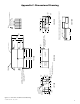
TOP VIEW
LEFT VIEW
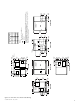
FRONT VIEW
BOTTOM VIEW
RIGHT VIEW
BACK VIEW
ERV1500i Corner Weights
PTS
A
B
C
D
Total
LBS
143
149
124
129
545
KG
64.9
67.6
56.2
58.5
247.2
Notes:
Dimensions in [ ] are millimeters.
Center of gravity
Optional
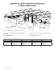
Note: On vertical discharge units, ductwork is to be attached to accessory roofcurb only.
On horizontal discharge units, field supplied flanges are to be attached to horizontal discharge
openings and ductwork is to be attached to the flanges.
Note: A minimum of 42.000” [1,067] clearance from any obstruction is required for removal of
energy recovery module, fans and filters.
SA-B
Figure C2: ERV1500i unit dimensional drawing