
Specifications

VCES-ERV-IOM-3B – Indoor ERV
15
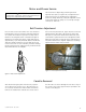
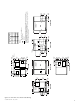
Perimeter Seal Replacement
To replace the perimeter seal, the enthalpy wheel must be
removed from the frame. Disconnect the service connector
to the drive motor of the enthalpy wheel cassette. Remove
the cassette from the unit and stand the assembly on the
floor. Remove the dust cap (#1, Figure 11) from the bear-
ing on the drive motor side of the cassette. Remove the
bolt (#2, Figure 11) from the end of the wheel shaft with a
socket or wrench on the drive motor side. Repeat this pro-
cedure for the other side of the cassette assembly. Remove
the four bolts (#3, Figure 11) with a socket or wrench. Re-
move the beam and bearing assembly from the end of the
wheel shaft. Loosen the four Nyloc nuts (#1, Figure 12)
holding the drive motor using a socket or wrench. Rotate
the drive motor in the slots to loosen the drive belt and
remove the belt. Lift the enthalpy wheel out of the frame
with assistance and set aside. Remove the perimeter seal
halves (#4, Figure 11) from the cassette frame assembly.
Install the two new perimeter seal halves by pressing them
into place, cutting to the correct length as necessary. The
perimeter seals are non-adjustable. Complete the installa-
tion by reversing the above procedure.
Face Seal Replacement and Adjustment
To replace the face seals, the cassette assembly must be
removed from the unit. Disconnect the service connector
to the drive motor of the enthalpy wheel cassette. Remove
the cassette from the unit and stand up on the floor. Re-
move the screws holding the face seals (#5, Figure 11).
Replace the two seals (supply and exhaust sides), cutting
to length as required. Adjust the seals in the slots so that
the brush just touches the face of the wheel. Complete
the installation by reversing the above procedure.
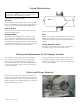
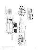
Enthalpy Wheel Drive Belt Replacement and
Tensioning Adjustment
The enthalpy wheel drive belt can be tightened by only
sliding the cassette assembly part way out of the unit.
Disconnect the service connector to the drive motor of the
enthalpy wheel cassette. Slide the cassette assembly out
of the unit enough to access the drive motor. Loosen the
four Nyloc nuts (#1, Figure 12) holding the drive motor
using a socket or wrench. Rotate the drive motor to loosen
the belt and replace the belt if necessary. Rotate the drive
motor in the slots to tighten the drive belt. Secure the
motor in its new location by tightening the four Nyloc
nuts. (#1, Figure 12). Complete the installation by revers-
ing the above procedure.
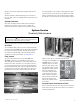
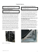
Cassette Service
WARNING
Disconnect the main power switch to the unit before per-
forming service and maintenance procedures.
!
CAUTION
When handling the enthalpy wheel, ensure not to dam-
age the face of the wheel.
CAUTION
When handling the enthalpy wheel, ensure not to dam-
age the face of the wheel.
Figure 11: Cassette and drive
Figure 12: Tension adjustment