
Specifications

VCES-ERV-IOM-3B – Indoor ERV
12
Dampers can then be adjusted to equalize flow rated in
the ducts.
Another method of airflow balancing is to measure the
pressure drop across the enthalpy wheel and correlate it to
an airflow.
Setting Flow Rate
Flow rates should be balanced with units operating on
high speed. A damper must be used to establish the
minimum duct pressure required so fans do not operate
in overload regions. For belt drive units, adjust the motor
sheave for the best fan speed. Set the dampers to estab-
lish the minimum duct pressure required. Further adjust
the dampers to reduce flow to the desired, balanced rate.
Quarterly maintenance (every three months) should include:
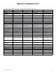
Air Filters
The standard medium efficiency filters and optional high
efficiency filters (ERV3000i only) are disposable and should
be replaced every three months. More frequent replace-
ment may be required under extremely dirty operating
conditions. For filter specifications see Appendix A.
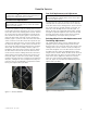
Filter Service
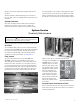
To remove the exhaust filters in the ERV1000i and
ERV2000i, remove the screw holding the filter access
door and slide the exhaust filter access door down to the
bottom of the unit. The filters are set in frames and can
be removed by pulling on the filter tabs and sliding them
forward and out of the unit. First, the right filter must be
removed, then the left filter must slide over to where the
right filter was, then pull it forward and out of the unit.
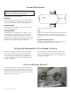
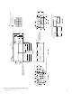
To replace the ERV1500i and
ERV3000i filters, remove the
enthalpy wheel access door.
Grasp the filter frame at the
left and right edges and pull
straight out. The filter frame
will slide completely out
of the unit. Slide the filters
up and out the top of the
frame. Slide the new filters
into the frame and slide the
frame back into the unit.
Replace the enthalpy wheel
access door.
Cassette Panels and Interior of Unit
Remove the filters from the unit. Wipe the foil faced insu-
lation surfaces and cassette panels with a soft cloth and
mild cleaning solution.
System Service
Quarterly Maintenance
WARNING
Disconnect the main power switch to the unit before per-
forming service and maintenance procedures.
!
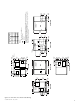
Figure 4: Filter access – ERV 1000i and ERV2000i
Figure 5: Filter access – ERV1500i and ERV3000i
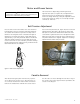
Figure 6: Replace filters –
ERV1500i and ERV3000i