
Specifications

VCES-ERV-IOM-3B – Indoor ERV
11
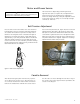
Preheat Frost Prevention
Preheat frost prevention is an outdoor air temperature
controlled function that allows for continuous ventilation
by ensuring a minimum entering air temperature (into the
enthalpy wheel) of 5°F [−15°C]. There are three fixed kW
capacity options available. For preheat capacity require-
ments, please use applicable ASHRAE formulas. Preheat
frost prevention can have two-stage, four-stage or SCR
control.
VSD (Variable Speed Drive) Frost Prevention
This variable speed frost prevention option is an exhaust
air temperature controlled function that allows for contin-
uous ventilation by reducing the enthalpy wheel rotational
speed. The rotational speed and therefore effectiveness of
the enthalpy wheel, is modulated to maintain an exhaust
air temperature of 33°F [1°C]. This modulation maintains
the wheel operating temperature at conditions that pre-
vent frost formation. Special consideration must be given
to applications where supply air is being heated, as the
heating capacity maximum condition will be during the
frost prevention cycle.
Before start-up, check the unit for obstructive packaging,
objects near or in blowers, dampers, enthalpy wheel, etc.
Once installation is complete, check all modes of opera-
tion to ensure that the unit is working properly. Close the
doors and check for operation on Low, Com and High
modes. Use a wall control or the dry contact switching to
run fan speeds as shown in Appendix E, Wall Control Con-
nection and Remote Fan Control.
Unit check points:
• Power connected, no ventilation call – Both fans are
off, defrost damper (if equipped) closes off fresh air
from outside.
• Power connected, low speed call (if equipped) –
Both fans on low speed, internal defrost damper (if
equipped) and closes recirculation opening. If unit is
single speed, it will come on that speed on a call for
low or high.
• Power connected, high speed call – Both fans on
high speed, defrost damper (if equipped) closes recir-
culation opening. If unit is single speed, it will come
on the speed on a call for low or high.
• Power connected, occupied timer/sensor connec-
tion open (factory installed jumper removed/unoc-
cupied mode) – Both fans are off, defrost damper (if
equipped) opens recirculation opening.
• Power connected, enthalpy control contacts closed,
unit ventilating – Wheel stops rotating, fans stay on
set speed, defrost damper (if equipped) is closed.
• Power connected, enthalpy control contacts closed,
unit not in ventilation mode – Wheel does not rotate,
fans come on low speed (if equipped), if unit is single
speed, it will come on that speed on a call for low or
high, defrost damper (if equipped) is closed (recircu-
lation defrost only).
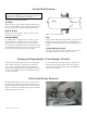
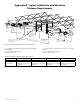
For proper performance the unit must operate with equal
supply and exhaust flow rates. Flow measuring stations
(FMS) and magnehelic gauges can be used to measure
and compare supply flow with exhaust flow. Appendix B
shows proper installation of the FMS in the “exhaust from
space” and “supply to space” ducts for measuring exhaust
and supply flows respectively.
It is important to locate the FMS in the “warm side” duc-
twork as described above to minimize the effect of dif-
ferences in air density, especially when balancing during
extremely cold outside conditions. Air density variations
can effect the FMS by more that 15%.
The FMS should be located downstream from straight
sections of duct and not immediately after fans or obstruc-
tions that will cause turbulent flow. Appendix B illustrates
the minimum distance from fan elbows for best operation.
Flow control dampers should be installed downstream
from the FMS so flow through the FMS is not disturbed.
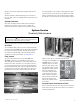
Sequence of Operation
Airflow Balancing
IMPORTANT
On initial power up, the unit will perform a system check
and operate at high speed for five seconds.