
User manual


Table Of Contents
- 1. Introduction
- 2. Technical data
- 3. For your safety
- 4. Transport, storage and disposal
- 5. Commissioning
- 6. Functional description
- 6.1 Operation
- 6.2 The Work mode
- 6.3 Parameter mode
- 6.4 Configuration mode
- 6.5 Factory settings (“default”)
- 6.6 Contrast
- 6.7 Replacing the soldering tip
- 6.8 Changing the Heating Element
- 6.9 Sensitive components
- 7. Error diagnosis and remedy
- 8. Maintenance
- 9. Replacement parts
- 10. Warranty
i-CON 1 / 41
3BA00180 • 28.04.2008 • Rev. 1
Operating instructions
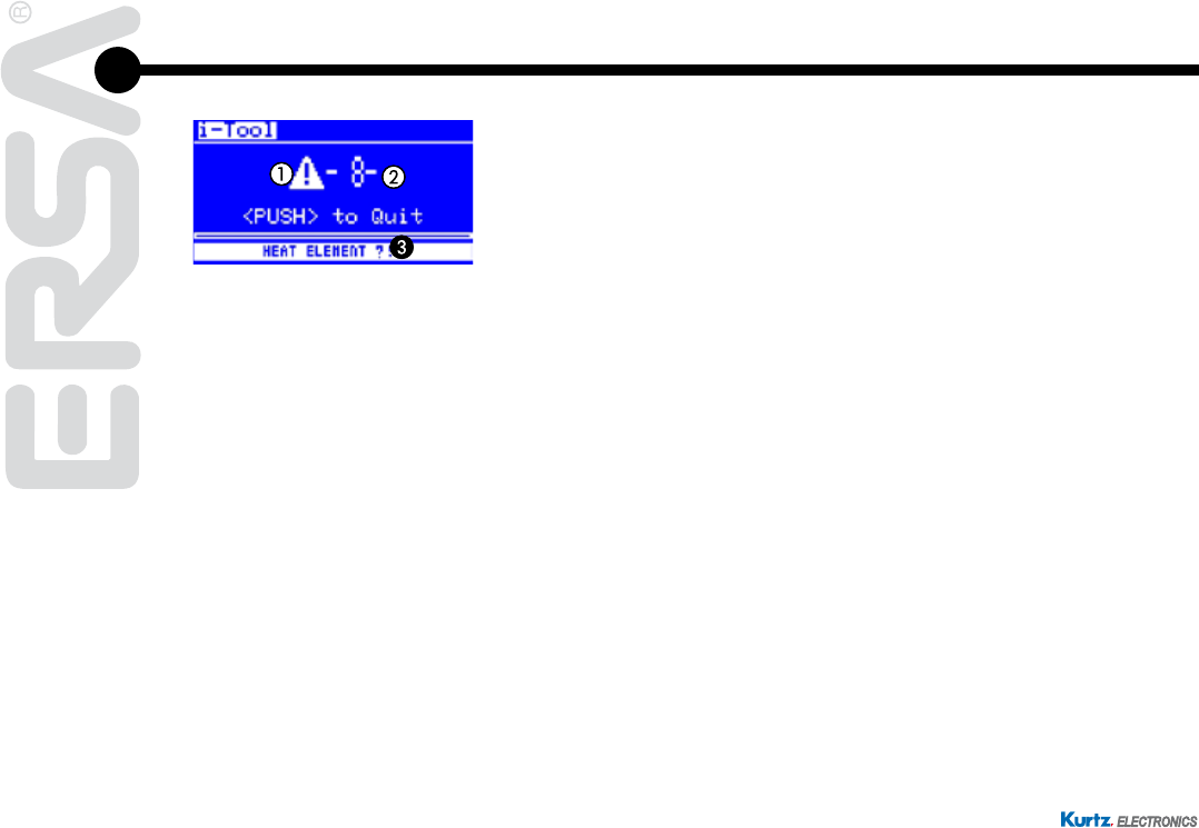
7.5 Error Messages
The i-CON 1 carries out an automatic error diagnosis. The result of a diagnosis is
displayed as an error code: The triangular pictograph a appears in the display of
the soldering station. The error code b is displayed as a number between 2 and 99.
Additionally, an information text 3 is displayed in the bottom line. The error codes
arelistedinthefollowingtable.Errormessageshavetobeconrmedwiththei-OP.
Aftertheerrorhasbeeneliminatedandtheerrormessagehasbeenconrmed,the
connected soldering tool will be heated again.