
User manual


Table Of Contents
- 1. Introduction
- 2. Technical data
- 3. For your safety
- 4. Transport, storage and disposal
- 5. Commissioning
- 6. Functional description
- 6.1 Operation
- 6.2 The Work mode
- 6.3 Parameter mode
- 6.4 Configuration mode
- 6.5 Factory settings (“default”)
- 6.6 Contrast
- 6.7 Replacing the soldering tip
- 6.8 Changing the Heating Element
- 6.9 Sensitive components
- 7. Error diagnosis and remedy
- 8. Maintenance
- 9. Replacement parts
- 10. Warranty
i-CON 1 / 21
3BA00180 • 28.04.2008 • Rev. 1
Operating instructions
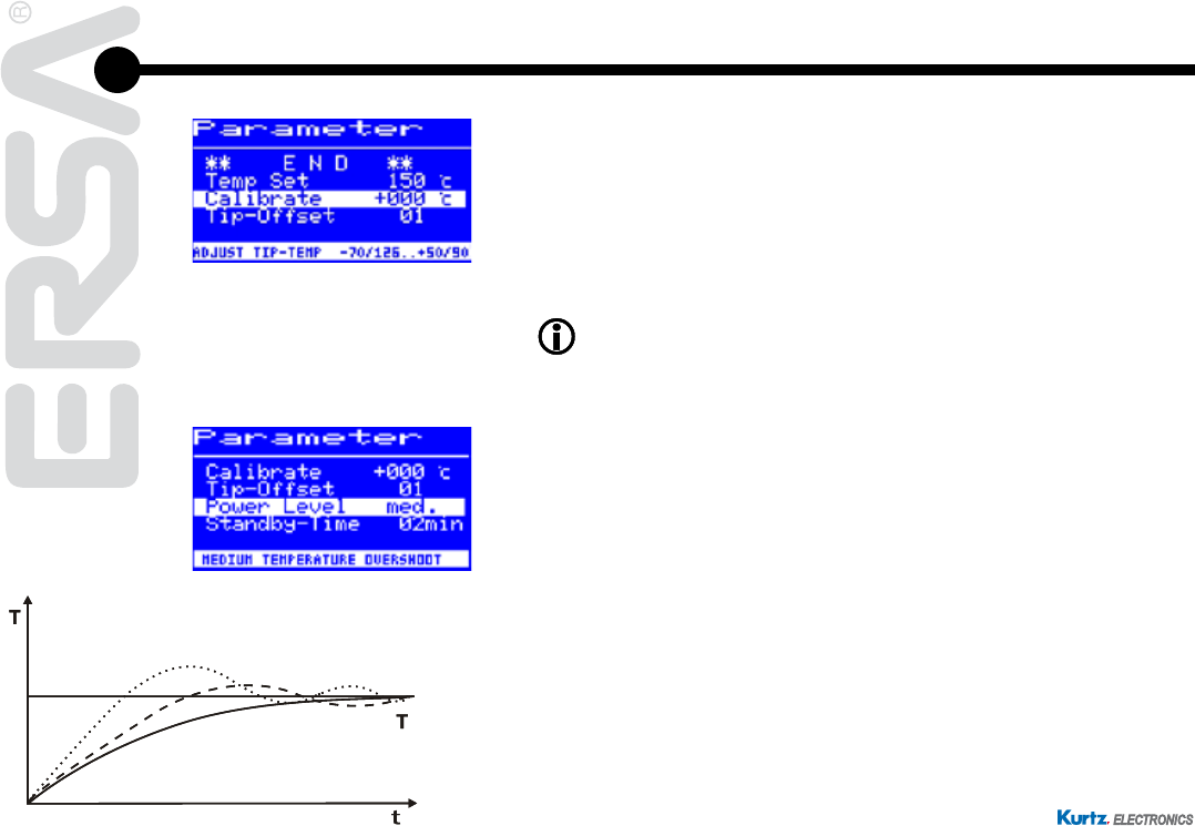
6.3.6 Calibration temperature
■
Determine the soldering tip temperature with a calibrated measuring
device (e.g. ERSA DTM 100).
■
Compare the two displayed values of i-CON 1 and the measuring de-
vice.
■
Calculatethetemperaturedifference:∆T=T
i-CON 1
– T
measuring device
■
Setthecalculatedtemperaturedifference∆T(withalgebraicsignvia
the rotary motion at the i-OP) in the menu item [Calibrate].
Quiet air conditions are important for the prevention of measurement
errors.
6.3.7 Power Level
Thisfunctionenablestheusertoinuencetheregulatingbehaviourofthestation,
whereby the heating and after heating behaviour of the station can be matched to
the actual application. Three settings are possible: [high], [med.] and [low].
• [Low]: Minimum post-heating characteristics. For soldering works with
low heat demand.
• [Med.]: Increased post-heating characteristics.
For soldering works with
increased heat demand.
• [High]: Maximum post-heating characteristics.
For soldering works with
very high heat demand.
High
Set
Med
Low
High
Set
Med
Low