
User manual


Table Of Contents
- 1. Introduction
- 2. Technical data
- 3. For your safety
- 4. Transport, storage and disposal
- 5. Commissioning
- 6. Functional description
- 6.1 Operation
- 6.2 The Work mode
- 6.3 Parameter mode
- 6.4 Configuration mode
- 6.5 Factory settings (“default”)
- 6.6 Contrast
- 6.7 Replacing the soldering tip
- 6.8 Changing the Heating Element
- 6.9 Sensitive components
- 7. Error diagnosis and remedy
- 8. Maintenance
- 9. Replacement parts
- 10. Warranty
i-CON 1 / 14
3BA00180 • 28.04.2008 • Rev. 1
Operating instructions
6. Functional description
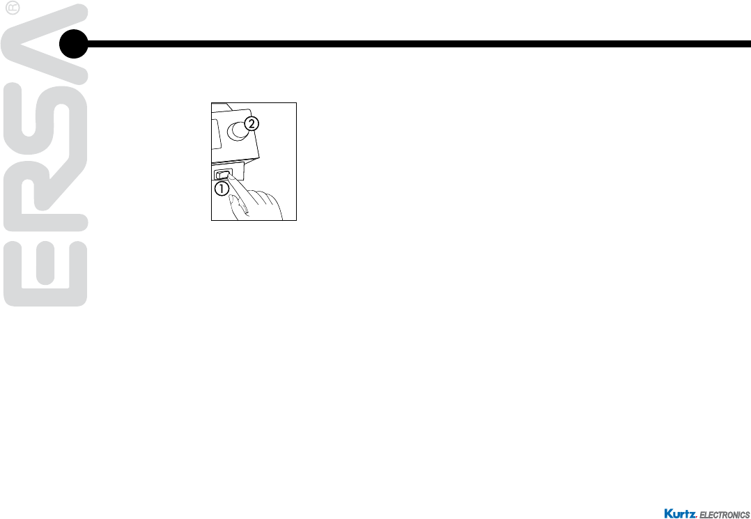
6.1 Operation
The soldering station is switched on and off by the mains switch on the front side a.
The soldering station is controlled via a rotary encoder b with pushbutton function.
It is called i-OP. The i-OP makes it possible to select desired functions or to change
values. Clockwise turning results in higher values and counter-clockwise turning
in lower values. Slow turning effects change in increments of one. Quick turning
changes the selected values in increments of 10/50/100 (depending on the corre-
sponding parameter).
The i-OP has an additional pushbutton function. Via this pushbutton function (push-
ing),theselectedparametersandvaluesareconrmedandbecomeeffectivefor
the station. All setting steps and measured values are displayed in plain text in a
clearly structured display window, which is simply referred to as “Display”.
0
_
ON
0
_
ON