
Install Instructions
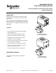
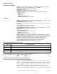
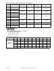
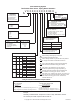
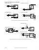
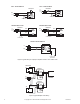
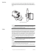
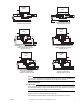
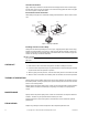
Table Of Contents
- Application
- Features
- SPECIFICATIONS
- Service
- System Static Pressure Limits
- Close-off
- Fluid/Ambient Temperature Limits
- S eat Leakage
- Voltage
- Power Requirements
- End Switch
- Control Signal
- Timing, Full Open to Full Close
- Materials
- Ambient Temperature Limits:
- Humidity
- Agency Listings
- Shipping Weight (Actuator/Valve Assembly)
- Table-1 Valve Body and Actuators Model Chart
- Table-2 Flow Coefficients & Maximum Close-Off Pressure Differential
- Table-3 Water Valve Sizing Table*
- TYPICAL APPLICATION (wiring diagram)
- INSTALLATION
- . Electrical shock hazard! Disconnect power before installation to prevent electrical shock or equipment damage.
- . Avoid locations where excessive moisture, corrosive fumes, explosive vapors, or vibration are present.
- . When making lead connections within the actuator, use caution not to put leads or connectors below the motor.
- This is a class B (European Classification) product. In a domestic environment this product may cause radio interference in which case the user may be required to take adequate measures.
- Use in systems which have substantial make-up water (open systems) is not recommended. Follow proper water treatment practices and system procedures. Refer to document F-26080-1 for Water and Steam EN205 Guidelines.
- Do not solder with actuator in place, or with paddle against seat, as the heat can damage the unit. Before soldering, move the manual open lever into Open position then remove the actuator from the body. Orient paddle so it is not against a seat.
- Do not use the valve body to manually open the actuator as damage to the valve actuator will result.
- CHECKOUT
- 1. Make sure the valve stem rotates freely before and after installing the actuator.
- 2. If the stem does not operate freely it may indicate that the stem was damaged and may require that the valve be repaired or replaced.
- 3. After the piping is under pressure, check the valve body and the connections for leaks.
- 4. After the valve and actuator are installed, power the actuator and check the operation.
- THEORY OF OPERATION
- MAINTENANCE
- FIELD REPAIR
- DIMENSIONAL DATA

F-26496-7 Copyright 2010 Schneider Electric All Rights Reserved. 7
INSTALLATION
Inspection
Inspect the package for damage. If package is damaged, notify the appropriate carrier
immediately. If undamaged, open the package and inspect the device for obvious damage.
Return damaged products.
Requirements
• Tools (not provided)
— Wrench 1 to 1-5/8" (if threaded valve)
— Soldering equipment (if sweat fit) or flare
• Training: Installer must be a qualified, experienced technician
• Other accessories as appropriate
Precautions
General
W A R N I N G
• Electrical shock hazard! Disconnect power before installation to prevent electrical shock
or equipment damage.
• Make all connections in accordance with the electrical wiring diagram and in accordance
with national and local electrical codes. Use copper conductors only.
• All conductors shall be provided with insulation rated for the highest voltage motor and
end switch circuits.
C A U T I O N
• Avoid locations where excessive moisture, corrosive fumes, explosive vapors, or
vibration are present.
• Avoid electrical noise interference. Do not install near large conductors, electrical
machinery, or welding equipment.
• When making lead connections within the actuator, use caution not to put leads or
connectors below the motor.
Federal Communications Commission (FCC)
N O T E
This equipment has been tested and found to comply with the limits for a Class B digital
device, pursuant to Part 15 of the FCC Rules. These limits are designed to provide
reasonable protection against harmful interference in residential installations. This
equipment generates, uses, and can radiate radio frequency energy and may cause harmful
interference if not installed and used in accordance with the instructions. Even when
instructions are followed, there is no guarantee that interference will not occur in a particular
installation. If this equipment causes harmful interference to radio and television reception—
which can be determined by turning the equipment off and on—the user is encouraged to
try to correct the interference by one or more of the following measures:
• Reorient or relocate the receiving antenna.
• Increase the separation between the equipment and receiver.
• Connect the equipment to an outlet on a circuit different from that to which the receiver
is connected.
• Consult the dealer or an experienced radio/television technician for help.
Canadian Department of Communications (DOC)
N O T E
This class B digital apparatus meets all requirements of the Canadian Interference-Causing
Equipment Regulations.
European Standard EN 55022
W A R N I N G
This is a class B (European Classification) product. In a domestic environment this product
may cause radio interference in which case the user may be required to take adequate
measures.