
Install Instructions
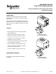
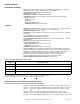
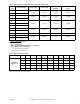
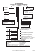
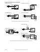
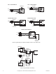
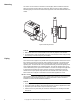
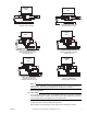
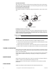
Table Of Contents
- Application
- Features
- SPECIFICATIONS
- Service
- System Static Pressure Limits
- Close-off
- Fluid/Ambient Temperature Limits
- S eat Leakage
- Voltage
- Power Requirements
- End Switch
- Control Signal
- Timing, Full Open to Full Close
- Materials
- Ambient Temperature Limits:
- Humidity
- Agency Listings
- Shipping Weight (Actuator/Valve Assembly)
- Table-1 Valve Body and Actuators Model Chart
- Table-2 Flow Coefficients & Maximum Close-Off Pressure Differential
- Table-3 Water Valve Sizing Table*
- TYPICAL APPLICATION (wiring diagram)
- INSTALLATION
- . Electrical shock hazard! Disconnect power before installation to prevent electrical shock or equipment damage.
- . Avoid locations where excessive moisture, corrosive fumes, explosive vapors, or vibration are present.
- . When making lead connections within the actuator, use caution not to put leads or connectors below the motor.
- This is a class B (European Classification) product. In a domestic environment this product may cause radio interference in which case the user may be required to take adequate measures.
- Use in systems which have substantial make-up water (open systems) is not recommended. Follow proper water treatment practices and system procedures. Refer to document F-26080-1 for Water and Steam EN205 Guidelines.
- Do not solder with actuator in place, or with paddle against seat, as the heat can damage the unit. Before soldering, move the manual open lever into Open position then remove the actuator from the body. Orient paddle so it is not against a seat.
- Do not use the valve body to manually open the actuator as damage to the valve actuator will result.
- CHECKOUT
- 1. Make sure the valve stem rotates freely before and after installing the actuator.
- 2. If the stem does not operate freely it may indicate that the stem was damaged and may require that the valve be repaired or replaced.
- 3. After the piping is under pressure, check the valve body and the connections for leaks.
- 4. After the valve and actuator are installed, power the actuator and check the operation.
- THEORY OF OPERATION
- MAINTENANCE
- FIELD REPAIR
- DIMENSIONAL DATA

4 Copyright 2010 Schneider Electric All Rights Reserved. F-26496-7
Example:
Assembly: VT2213G13A020. Components: VT2213 = Body. AG13A020= Actuator.
The actuator part number is prefixed with the letter "A".
Part Numbering System
Two Position Zone Valves, Spring Return Actuators
V X X X X X X X X X XX X
Voltage
A = 24 VAC, 50/60 HZ
B = 110 VAC, 60 HZ, 120 VAC, 50 HZ
D = 208 VAC, 50/60 HZ
T = 277 VAC, 50/60 HZ
U = 230 VAC, 50 HZ and 240 VAC, 60 HZ
Electrical Leads
00 = 6" Motor Wires
01 = Terminal Block with End Switch
(General Temp., 24 VAC only)
02 = 18" (Standard) Wire Leads
Options
0 = No Options
A = End Switch
Actuator Type
G = On/Off (General Close-Off)
H = On/Off (High Close-off)
No. 2-way 3-way
1 = 1.0 1.5 1/2" 1, 2, 3, 5
3/4" 4
2 = 2.5 3.0 1/2" 1, 2, 3, 5
3/4" 1, 2, 3, 4
1/2" 1, 2, 3, 5
3 = 3.5 4.0 3/4" 1, 2, 3, 4
1" 1
5 = 5.0 5.0 3/4" 1, 2, 3
1" 1
7 = 7.5 7.5 3/4" 1, 2, 3
8.0 8.0 1" 1, 2, 3
1-1/4" 1
Connection Type Availability
1 = Sweat 1/2", 3/4", 1", 1-1/4"
2 = Threaded NPT 1/2", 3/4", 1"
3 = Threaded Rp (metric) 1/2", 3/4", 1"
4 = Inverted Flare (Retrofit) 3/4"
5 = SAE Flare 1/2"
Body Type &
Temperature
T = On/Off (General)
S = On/Off (Steam)
High temperature
actuator must be used.
Configuration
2 = 2-Way
3 = 3-Way
Valve Size
2 = 1/2"
3 = 3/4"
4 = 1"
5= 1-1/4"
Temperature Ratings
3 = General Temperature
4 = High Temperature
Body & Actuator Combination Requirements
Temperature Configurations
Body Configuration
V T X X X X
Actuator Spring Return Mode
A X X 3 X X X X
T = General
S = Steam
If body configuration is T, actuator temp rating can be 3 or 4.
If body configuration is S, actuator temp rating must be 4.
3 = General Temperature
4 = High Temperature
If actuator temp rating is 3, body style must be T.
If actuator temp rating is 4, body style can be S or T.
Size Connection Type
1
2
3
4
1 = Normally Closed 2-way and 3-way
2 = Normally Open 2-way only
Spring Return Availability
5
When ordering valve body only: use the first
six positions to configure the valve.
1
2
TAC inverted flare fittings must be ordered separately.
See actuator accessories for fitting part numbers.
3
5
End switch is not available for 277 Vac models if
actuator temperature rating is high temperature (4).
4
When ordering actuator only use the last seven positions
to configure the actuator. Prefix with the letter "A".
Actuators with Terminal blocks require endswitch and
the endswitch is 24 Vac @ 101 mA min. -5A max.
6
End switch is 24 - 240Vac @ 101 mA min. to 5 A max. and
9-30 Vdc @ 100 mA max for actautors rated 240V or less.
End switch is 277Vac @ 101 mA min. to 5A max for
actuators rated 277V.
5
6
CV Size