
Submittal Sheet
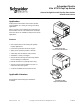
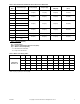
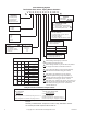
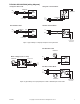
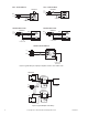
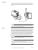
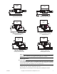
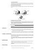
Table Of Contents
- Application
- Features
- SPECIFICATIONS
- Service
- System Static Pressure Limits
- Close-off
- Fluid/Ambient Temperature Limits
- S eat Leakage
- Voltage
- Power Requirements
- End Switch
- Control Signal
- Timing, Full Open to Full Close
- Materials
- Ambient Temperature Limits:
- Humidity
- Agency Listings
- Shipping Weight (Actuator/Valve Assembly)
- Table-1 Valve Body and Actuators Model Chart
- Table-2 Flow Coefficients & Maximum Close-Off Pressure Differential
- Table-3 Water Valve Sizing Table*
- TYPICAL APPLICATION (wiring diagram)
- INSTALLATION
- . Electrical shock hazard! Disconnect power before installation to prevent electrical shock or equipment damage.
- . Avoid locations where excessive moisture, corrosive fumes, explosive vapors, or vibration are present.
- . When making lead connections within the actuator, use caution not to put leads or connectors below the motor.
- This is a class B (European Classification) product. In a domestic environment this product may cause radio interference in which case the user may be required to take adequate measures.
- Use in systems which have substantial make-up water (open systems) is not recommended. Follow proper water treatment practices and system procedures. Refer to document F-26080-1 for Water and Steam EN205 Guidelines.
- Do not solder with actuator in place, or with paddle against seat, as the heat can damage the unit. Before soldering, move the manual open lever into Open position then remove the actuator from the body. Orient paddle so it is not against a seat.
- Do not use the valve body to manually open the actuator as damage to the valve actuator will result.
- CHECKOUT
- 1. Make sure the valve stem rotates freely before and after installing the actuator.
- 2. If the stem does not operate freely it may indicate that the stem was damaged and may require that the valve be repaired or replaced.
- 3. After the piping is under pressure, check the valve body and the connections for leaks.
- 4. After the valve and actuator are installed, power the actuator and check the operation.
- THEORY OF OPERATION
- MAINTENANCE
- FIELD REPAIR
- DIMENSIONAL DATA

Printed in U.S.A. 6-10 Copyright 2010 Schneider Electric All Rights Reserved. F-26496-7
Application
PopTop Series valve bodies and actuators provide
easy installation for a variety of heating and cooling
applications.
Valve’s actuator can be installed after valve body has
been installed onto fan coil, baseboard or air handler.
VS Series valves are available for low pressure steam
applications.
Features
• Direct replacement for all existing two-position
PopTop applications
• Hysteresis synchronous motor for long life
• Spring return operation provides a fail-safe
• Valve body rated for 300 psi static pressure
• Available in a variety of voltages
• Actuator mounts directly onto valve body without
need for linkages or calibration
• Manual override lever (normally closed only)
• Actuator can be replaced without any tools, or
removal of valve from system
• VS Series available for low pressure steam
Applicable Literature
EN-205 Water and Steam System Guidelines,
F-26080-1.
Schneider Electric
Erie VT/VS PopTop Series
General & High Close-Off PopTop Zone Valves
General Instructions
VT/VS Series with
High Close-Off Actuator
VT/VS Series with
General Close-Off Actuator