
Submittal Sheet
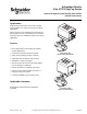
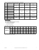
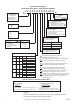
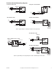
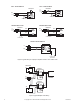
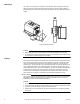
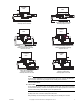
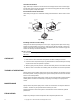
Table Of Contents
- Application
- Features
- SPECIFICATIONS
- Service
- System Static Pressure Limits
- Close-off
- Fluid/Ambient Temperature Limits
- S eat Leakage
- Voltage
- Power Requirements
- End Switch
- Control Signal
- Timing, Full Open to Full Close
- Materials
- Ambient Temperature Limits:
- Humidity
- Agency Listings
- Shipping Weight (Actuator/Valve Assembly)
- Table-1 Valve Body and Actuators Model Chart
- Table-2 Flow Coefficients & Maximum Close-Off Pressure Differential
- Table-3 Water Valve Sizing Table*
- TYPICAL APPLICATION (wiring diagram)
- INSTALLATION
- . Electrical shock hazard! Disconnect power before installation to prevent electrical shock or equipment damage.
- . Avoid locations where excessive moisture, corrosive fumes, explosive vapors, or vibration are present.
- . When making lead connections within the actuator, use caution not to put leads or connectors below the motor.
- This is a class B (European Classification) product. In a domestic environment this product may cause radio interference in which case the user may be required to take adequate measures.
- Use in systems which have substantial make-up water (open systems) is not recommended. Follow proper water treatment practices and system procedures. Refer to document F-26080-1 for Water and Steam EN205 Guidelines.
- Do not solder with actuator in place, or with paddle against seat, as the heat can damage the unit. Before soldering, move the manual open lever into Open position then remove the actuator from the body. Orient paddle so it is not against a seat.
- Do not use the valve body to manually open the actuator as damage to the valve actuator will result.
- CHECKOUT
- 1. Make sure the valve stem rotates freely before and after installing the actuator.
- 2. If the stem does not operate freely it may indicate that the stem was damaged and may require that the valve be repaired or replaced.
- 3. After the piping is under pressure, check the valve body and the connections for leaks.
- 4. After the valve and actuator are installed, power the actuator and check the operation.
- THEORY OF OPERATION
- MAINTENANCE
- FIELD REPAIR
- DIMENSIONAL DATA

2 Copyright 2010 Schneider Electric All Rights Reserved. F-26496-7
SPECIFICATIONS
Valve Body Assembly
Service Hot and chilled water models, up to 50% glycol. Steam models up to 15 psi (both
valve body and valve actuator must be rated for high temperature).
System Static Pressure Limits 300 psi (2068.4 kPa).
Close-off Refer to Table-2.
Fluid/Ambient Temperature Limits Refer to Table-1.
Seat Leakage ANSI class IV (0.01%) with pressure at inlet (B-port/A-port, if 3-way).
Body Forged brass.
Stem Nickel-plated.
Seat Brass.
Paddle (VT series) Buna N.
Paddle (VS series) Highly saturated nitrile.
Actuator
Voltage 24 Vac @ 50/60 Hz. 110 Vac @ 50 Hz. and 120 Vac @ 60 Hz., 230 Vac @ 50 Hz.
and 240 Vac @ 60 Hz., 208 Vac @ 50/60 Hz., 277 Vac @ 50/60 Hz.
Power Requirements 6.5 watts, 7.5 Va.
End Switch 24 - 240 Vac Models: 24 - 240 Vac/101 mA min. to 5A max, and 9 - 30 Vdc @
100 mA max.
277 Vac Models: 277 Vac/101 mA min. to 5A max.
Control Signal On/off, 2 position, spring return.
Timing, Full Open to Full Close 25 Sec max for 60 Hz; 30 Sec max for 50 Hz; and 9 Sec
max spring return.
Materials Stainless steel base plate, aluminum cover.
Ambient Temperature Limits:
Shipping & Storage, -40 to 160 °F (-40 to 71°C).
Operating, Refer to Table-1.
Humidity 5 to 95% relative humidity, non-condensing.
Agency Listings UL873: Underwriters laboratories (File #E9429 Catagory Temperature
Indicating and Regulating Equipment). CUL: UL Listed for use in Canada by Underwriters
Laboratory. Canadian Standards C22.2 No. 24. European Community: EMC Directive
(89/336/EEC). Low Voltage Directive (72/23/EEC). Australia: This product meets
requirements to bear the C-Tick Mark according to the terms specified by the
Communications Authority under the Radio Communications Act of 1992.
Shipping Weight (Actuator/Valve Assembly) 2.25 lbs (1020 g).
a: For steam applications both valve body and valve actuator must be rated for high temperature.
Example: VS2213G14A020 = Assembly. VS
2213 = Valve body. AG14A020 = Actuator.
Accessories for Inverted Flare Connection Valves
3/4" inverted flare bodies accept the following adapters to copper pipe:
436-214-1 Union nut & elbow assembly, female for 1/2" (5/8" O.D.) copper, 15/16" long
436-220 Union nut & coupling assembly, female for 1/2" (5/8" O.D.) copper, 1-1/16" long
436-252 Union nut & coupling assembly, female for 3/4" (7/8" O.D.) copper, 1-27/32"
long
436-229-3 Union nut & nipple assembly, male for 1/2" (5/8" O.D.) copper, 3" long
436-214-4 Union nut & elbow assembly, male for 1/2" (5/8" O.D.) copper, 1-15/16" long
436-256 Union nut & coupling assembly, female for 1" (1-1/8" O.D.) copper, 1-3/8" long
Table-1 Valve Body and Actuators Model Chart
Model Temperature Range
VTXXXX 32×to 200×F (fluid) @ 104×F (Ambient) (0to93×C @ 40×C)
VSXXXX 32× to 250×F (fluid) @ 169×F (Ambient) (0 to 121×C @ 76 ×C), and/or 15 PSI (103 kPa) Steam
a
AXX3XXX 32× to 200×F (fluid) @ 104 ×F (Ambient) (0 to 93×C @ 40×C)
AXX4XXX 32× to 250×F (fluid) @ 169×F (Ambient) (0 to 121×C @ 76×C), and/or 15 PSI (103 kPa) Steam
a