
Submittal Sheet
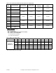
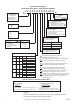
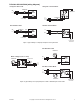
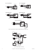
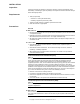
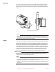
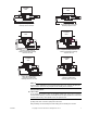
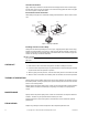
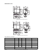
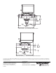
Table Of Contents
- Application
- Features
- SPECIFICATIONS
- Service
- System Static Pressure Limits
- Close-off
- Fluid/Ambient Temperature Limits
- S eat Leakage
- Voltage
- Power Requirements
- End Switch
- Control Signal
- Timing, Full Open to Full Close
- Materials
- Ambient Temperature Limits:
- Humidity
- Agency Listings
- Shipping Weight (Actuator/Valve Assembly)
- Table-1 Valve Body and Actuators Model Chart
- Table-2 Flow Coefficients & Maximum Close-Off Pressure Differential
- Table-3 Water Valve Sizing Table*
- TYPICAL APPLICATION (wiring diagram)
- INSTALLATION
- . Electrical shock hazard! Disconnect power before installation to prevent electrical shock or equipment damage.
- . Avoid locations where excessive moisture, corrosive fumes, explosive vapors, or vibration are present.
- . When making lead connections within the actuator, use caution not to put leads or connectors below the motor.
- This is a class B (European Classification) product. In a domestic environment this product may cause radio interference in which case the user may be required to take adequate measures.
- Use in systems which have substantial make-up water (open systems) is not recommended. Follow proper water treatment practices and system procedures. Refer to document F-26080-1 for Water and Steam EN205 Guidelines.
- Do not solder with actuator in place, or with paddle against seat, as the heat can damage the unit. Before soldering, move the manual open lever into Open position then remove the actuator from the body. Orient paddle so it is not against a seat.
- Do not use the valve body to manually open the actuator as damage to the valve actuator will result.
- CHECKOUT
- 1. Make sure the valve stem rotates freely before and after installing the actuator.
- 2. If the stem does not operate freely it may indicate that the stem was damaged and may require that the valve be repaired or replaced.
- 3. After the piping is under pressure, check the valve body and the connections for leaks.
- 4. After the valve and actuator are installed, power the actuator and check the operation.
- THEORY OF OPERATION
- MAINTENANCE
- FIELD REPAIR
- DIMENSIONAL DATA

Schneider Electric
1354 Clifford Avenue
P.O. Box 2940
Loves Park, IL 61132-2940
www.schneider-electric.com/buildings
On October 1st, 2009, TAC became the Buildings business of its parent company Schneider Electric. This document reflects the visual identity of Schneider Electric,
however there remains references to TAC as a corporate brand in the body copy. As each document is updated, the body copy will be changed to reflect appropriate
corporate brand changes.
Copyright 2010, Schneider Electric
All brand names, trademarks and registered
trademarks are the property of their respective
owners. Information contained within this
document is subject to change without notice.
F-26496-7
61
2 7/16"
61
2 7/16"
26
1"
57
2 1/4"
112
4 7/16"
B-PORT A-PORT
Figure-10 SAE - High Close-Off Style Actuator Shown
Figure-11 Inverted Flare - General Close-Off Style Actuator Shown
55
2 3/16"
33
1 5/16"
2-WAY
26
1 1/16"
3-WAY
32
1 1/4"
109
4 5/16"
B-PORT
A-PORT