
Submittal Sheet

F-26496-8 © Copyright 2013 Schneider Electric All Rights Reserved. 5
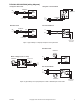
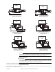
TYPICAL APPLICATION (wiring diagram)
To Aux. Circuit
Motor
End SwitchRed
To Aux. Circuit
Red
Black
Black
L1
(HOT)
L2
Erie Wire Leads
Motor
THERMOSTAT
THERMOSTAT
TH
L1
(HOT)
L2
Honeywell - Terminal Block
Erie Terminal Block
ES ES
To Aux. Circuit
24 V 5A max
THERMOSTAT
TH
L1
(HOT)
L2
Motor
TH
TR
ES ES
TH
TR
TH
TR
TR
End Switch
End Switch
Motor
End SwitchRed
To Aux. Circuit
Red
Black
Black
L1
(HOT)
L2
Honeywell - Wire Leads
THERMOSTAT
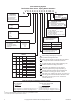
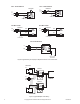
Figure-1 Typical Wiring of a PopTop to Replace a Honeywell Valve
Erie Terminal Block
Erie Wire Leads
5
6
4
White - Rodgers (1311 or 1321)
L1
(Hot)
L2
Motor
End Switch
To Aux. Circuit
65
4
3
2
1
5
4
6
To Aux. Circuit
24 V 5A max
THERMOSTAT
THERMOSTAT
Motor
End SwitchRed
Red
Black
Black
L1
(Hot)
L2
56
4
THERMOSTAT
TH
L1
(HOT)
L2
Motor
TR
ES ES
TH
End Switch
TH
TR
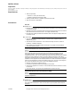
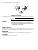
Figure-2 Typical Wiring of a PopTop to Replace a Flair or White-Rodgers 3-Wire Valve