
Submittal Sheet

10 © Copyright 2013 Schneider Electric All Rights Reserved. F-26496-8
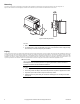
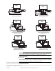
Inverted Flare Union Connection
Solder fittings onto pipe. Use solder with melting point below 600 °F. Mount valve to union nuts.
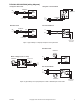
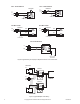
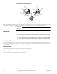
Installing Actuator on Valve Body
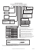
Slowly latch the manual operating lever in the open, engaged position (AG1 or AH1 only). Depress the release button (see Figure-7). Align the body with the actuator
to ensure the stem is inserted into the large mating hole on the bottom side of the actuator. Engage the actuator on the body and release the button.
T C A U T I O N
Do not use the valve body to manually open the actuator as damage to the valve actuator
will result.
CHECKOUT
1. Make sure the valve stem rotates freely before and after installing the actuator.
2. If the stem does not operate freely it may indicate that the stem was damaged and may
require that the valve be repaired or replaced.
3. After the piping is under pressure, check the valve body and the connections for leaks.
4. After the valve and actuator are installed, power the actuator and check the operation.
THEORY OF OPERATION
PopTop Series are two position spring return valves. When powered, the actuator moves to the desired position, tensing the spring return system. When power is
removed the actuator returns to the normal position.
PopTop Series two position spring return valves can be purchased with an optional built-in auxiliary SPDT end switch for interfacing or signaling; for example, zone
pump burner control.
MAINTENANCE
PopTop Series two position spring return valves are maintenance free. Replace defective modules. Actuator may be replaced without removing the valve.
Regular maintenance of the total system is recomended to assure sustained, optimum performance.
FIELD REPAIR
Replace any damaged or failed components with complete replacement unit.
Release
Button
Manual
Operating
Lever
Mating
Hole
High Close-Off (H)
General Close-Off (G)
Mating
Hole
Release
Button
Manual
Operating
Lever
Stem
Figure-7 PopTop Installation