
Install Instructions

© Copyright 2013, Schneider Electric
All brand names, trademarks and registered
trademarks are the property of their respective
owners. Information contained within this
document is subject to change without notice.
F-27204-6
www.schneider-electric.com
Schneider Electric
1354 Clifford Avenue
P.O. Box 2940
Loves Park, IL 61132-2940
Sweat Connections
T C A U T I O N
Do not solder with actuator in place, or with paddle against seat, as
the heat can damage the unit. Before soldering, move the manual
open lever into Open position then remove the actuator from the
body. Orient paddle so it is not against a seat.
Use lead or tin based solder with melting point below 600 °F. Do
not overheat. Direct flame tip away from valve. Cool valve quickly
with a wet cloth.
Body assembly can be submerged for leak testing prior to
attaching the actuator.
Threaded Connection
Apply Teflon tape to all but the last two threads of male pipe thread.
Hand screw the pipe into the valve, turning it as far as it will go. Use
a wrench to fully tighten the valve to the pipe. Do not over tighten
or strip the threads.
Inverted Flare Union Connection
Solder fittings onto pipe. Use solder with melting point below
600°F. Mount valve to union nuts.
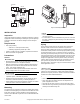
Installing Actuator on Valve Body
Slowly latch the manual operating lever in the open, engaged
position (AG1 or AH1 only). Depress the release button (see
Figure-7). Align the body with the actuator to ensure the stem is
inserted into the large mating hole on the bottom side of the
actuator. Engage the actuator on the body and release the button.
T C A U T I O N
Do not use the valve body to manually open the actuator as
damage to the valve actuator will result.
CHECKOUT
1. Make sure the valve stem rotates freely before and after
installing the actuator.
2. If the stem does not operate freely it may indicate that the stem
was damaged and may require that the valve be repaired or
replaced.
3. After the piping is under pressure, check the valve body and the
connections for leaks.
4. After the valve and actuator are installed, power the actuator
and check the operation.
THEORY OF OPERATION
PopTop Series are two position spring return valves. When
powered, the actuator moves to the desired position, tensing the
spring return system. When power is removed the actuator returns
to the normal position.
PopTop Series two position spring return valves can be purchased
with an optional built-in auxiliary SPDT end switch for interfacing or
signaling; for example, zone pump burner control.
MAINTENANCE
PopTop Series two position spring return valves are maintenance
free. Replace defective modules. Actuator may be replaced
without removing the valve.
Regular maintenance of the total system is recomended to assure
sustained, optimum performance.
FIELD REPAIR
Replace any damaged or failed components with complete
replacement unit.
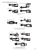
Figure-6e 3-Way Valve in
Diverting Configuration
Normally Closed to the
Coil.
Figure-6f 3-Way Valve in
Diverting Configuration
Normally Open to the
Coil.
POWER
OFF
A
B
Coil
A
B
POWER
OFF
Coil
POWER
OFF
A
B
Coil
POWER
OFF
A
B
Coil
POWER
OFF
AB
Coil
POWER
OFF
A
B
Coil
Figure-6b 2-Way Valve
With Normally Open
Actuator.
Figure-6c 3-Way Valve in
Mixing Configuration
Normally Closed to the Coil.
Figure-6d 3-Way Valve in
Mixing Configuration
Normally Open to the Coil.
Figure-6a 2-Way Valve
With Normally Closed
Actuator.
Release
Button
Manual
Operating
Lever
Mating
Hole
High Close-Off (H)
General Close-Off (G)
Mating
Hole
Release
Button
Manual
Operating
Lever
Stem
Figure-7 PopTop Installation.