
Install Instructions

F-27204-6 © Copyright 2013 Schneider Electric All Rights Reserved. 3
INSTALLATION
Inspection
Inspect the package for damage. If package is damaged, notify the
appropriate carrier immediately. If undamaged, open the package
and inspect the device for obvious damage. Return damaged
products.
Requirements
• Tools (not provided)
— Wrench 1 to 1-5/8" (if threaded valve)
— Soldering equipment (if sweat fit) or flare
• Training: Installer must be a qualified, experienced technician
• Other accessories as appropriate
Precautions
General
T W A R N I N G
• Electrical shock hazard! Disconnect power before installation to
prevent electrical shock or equipment damage.
• Make all connections in accordance with the electrical wiring
diagram and in accordance with national and local electrical
codes. Use copper conductors only.
• All conductors shall be provided with insulation rated for the
highest voltage motor and end switch circuits.
T C A U T I O N
• Avoid locations where excessive moisture, corrosive fumes,
explosive vapors, or vibration are present.
• Avoid electrical noise interference. Do not install near large
conductors, electrical machinery, or welding equipment.
• When making lead connections within the actuator, use caution
not to put leads or connectors below the motor.
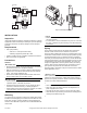
Mounting
The valves can be mounted in horizontal or vertical piping. When
installed in horizontal piping, the actuator must be above the valve
body. Refer to Figure-5. When installed in horizontal piping the
actuator can be tilted left or right but it must not be tilted below 85°
from vertical.
N O T E
• Make certain there is no overhead water source that may drip
onto valve actuator.
• In normal service, some condensation may occur on or around
the valve. A drip pan may be necessary or the valve body may
be insulated.
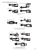
Piping
These valves must be piped so the paddle closes against the
direction of flow. Flow is from B to A. Refer to Figure-6a to
Figure-6f. When installing the actuator to a normally closed valve,
the actuator must be placed in the manually open position by using
the manual operating lever. The first time the valve is operated
electrically, the manual operating lever of the actuator will transfer
to the automatic position. The manual operating lever can be used
to allow flushing of the system after installation. The valves are
designed for application in closed hydronic heating and cooling
systems. High levels of dissolved oxygen and chlorine found in
open systems may attack the valve materials and result in
premature failure. Install over a drip pan if condensation in chilled
water applications occurs.
T C A U T I O N
Use in systems which have substantial make-up water (open
systems) is not recommended. Follow proper water treatment
practices and system procedures. Refer to document F-26080-1
for Water and Steam EN205 Guidelines.
N O T E
• Three-way valves always require a normally closed actuator.
• Three-way valves are always closed at the B port when no
power is applied to the motor.
• On power-up the valve closes to A port on three-way valves.
• Orient the three-way valve body as needed for normally open or
normally closed flow through coil.
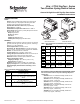
Figure-4 Typical Multiple Valve Wiring.
Thermostat
T1
T2
Valve #1
Valve #2
BURNER
CONTROL
TH
TR
ES
ES
TH/TR
T
T
L1
L2
TH
TR
ES
ES
TH/TR
85
360
Figure-5 Mounting Position.