
Install Instructions

© Copyright 2016, Schneider Electric
All brand names, trademarks and registered
trademarks are the property of their respective
owners. Information contained within this
document is subject to change without notice.
F-27204-7
North America (USA): +1 888 444 1311
Europe, Middle East & Africa (Sweden): +46 10 478
2000 Asia Pacific (Singapore): +65 6484 7877
product.support@schneider-electric.com
www.schneider-electric.com
Sweat Connections
C A U T I O N
Do not solder with actuator in place, or with paddle against seat, as the heat
can damage the unit. Before soldering, move the manual open lever into
Open position then remove the actuator from the body. Orient paddle so it
is not against a seat.
Use lead or tin based solder with melting point below 600 °F. Do
not overheat. Direct flame tip away from valve. Cool valve quickly
with a wet cloth.
Body assembly can be submerged for leak testing prior to
attaching the actuator.
Threaded Connection
Apply Teflon tape to all but the last two threads of male pipe thread.
Hand screw the pipe into the valve, turning it as far as it will go. Use
a wrench to fully tighten the valve to the pipe. Do not over tighten
or strip the threads.
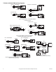
Inverted Flare Union Connection
Solder fittings onto pipe. Use solder with melting point below 600°F. Mount
valve to union nuts.
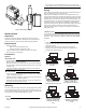
Installing Actuator on Valve Body
Slowly latch the manual operating lever in the open, engaged position (AG1
or AH1 only). Depress the release button (see Figure-7). Align the body
with the actuator to ensure the stem is inserted into the large mating hole
on the bottom side of the actuator. Engage the actuator on the body and
release the button.
C A U T I O N
Do not use the valve body to manually open the actuator as damage to the
valve actuator will result.
CHECKOUT
1. Make sure the valve stem rotates freely before and after installing the
actuator.
2. If the stem does not operate freely it may indicate that the stem was
damaged and may require that the valve be repaired or replaced.
3. After the piping is under pressure, check the valve body and the
connections for leaks.
4. After the valve and actuator are installed, power the actuator and check
the operation.
THEORY OF OPERATION
PopTop Series are two position spring return valves. When powered, the
actuator moves to the desired position, tensing the spring return system.
When power is removed the actuator returns to the normal position.
PopTop Series two position spring return valves can be purchased with an
optional built-in auxiliary SPDT end switch for interfacing or signaling; for
example, zone pump burner control.
MAINTENANCE
PopTop Series two position spring return valves are maintenance free.
Replace defective modules. Actuator may be replaced without removing
the valve.
Regular maintenance of the total system is recomended to assure
sustained, optimum performance.
FIELD REPAIR
Replace any damaged or failed components with complete replacement
unit.
Release
Button
Manual
Operating
Lever
Mating
Hole
High Close-Off (H)
General Close-Off (G)
Mating
Hole
Release
Button
Manual
Operating
Lever
Stem
Figure-7 PopTop Installation.
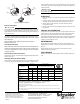
Commercial Reference
䜞Ԭ〦
Part Name
䫻
(Pb)
⊔
(Hg)
䭿
(Cd)
ޣԭ䬢
(Cr (VI))
ཐ⓪㚊㤥
(PBB)
ཐ⓪ӂ㤥䟐
(PBDE)
ኔ䜞Ԭ
Metal Parts
XOO O O O
ງᯏ䜞Ԭ
Plastic Parts
OOO O O O
⭫ᆆԬ
Electronic
OOO O O O
㓵㔼ૂ㓵㔼䱺Ԭ
Cables & cabling accessories
OOO O O O
ᵢ㺞Ṳדᦤ6-7Ⲻ㿺ᇐ㕌Ⱦ
2㺞⽰䈛ᴿᇩ⢟䍞൞䈛䜞Ԭᡶᴿൽ䍞ᶆᯏѣⲺ䠅ൽ൞*%7㿺ᇐⲺ䲆䠅㾷≸ԛсȾ
;㺞⽰䈛ᴿᇩ⢟䍞㠩ቇ൞䈛䜞ԬⲺḆжൽ䍞ᶆᯏѣⲺ䠅䎻࠰*%7㿺ᇐⲺ䲆䠅㾷≸Ⱦ
δԷѐ൞↚༺θṯᦤᇔ䱻߫ሯр㺞ѣᢉ;Ⲻᢶᵥഖ䘑㺂䘑ж↛䈪᱄Ⱦε
This table is made according to SJ/T 11364.
O: indicates that the concentration of hazardous substance in all of the homogeneous materials for this part is below the limit as
stipulated in GB/T 26572.
X: indicates that concentration of hazardous substance in at least one of the homogeneous materials used for this part is above the
limit as stipulated in GB/T 26572
Range Brand Product Description
AGXXXXXX
AHXXXXXX
ERIE ACTUATORS
AG GENERAL CLOSEOFF NO/NC CLASS-A/F SR/NSR
AH HIGH CLOSEOFF NO/NC CLASS-A/F SR/NSR
ᴿᇩ⢟䍞
- Hazardous Substances