
Submittal Sheet
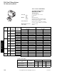
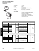

152 © Copyright 2006 TAC. All Rights Reserved F-27411-1
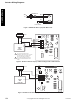
Actuator Wiring Diagrams
Wiring Diagrams
Figure 1 AG/AH TAC Erie PopTop with Wire Leads.
Figure 2 ATx3A00T TAC Erie PopTop 3-Wire Floating Actuator with Time-Out.
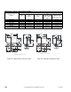
Figure 3 APx3A000 TAC Erie PopTop Three-Wire Proportional Actuator.
Motor
End SwitchRed
To Aux. Circuit
Red
Black
Black
L1
(HOT)
L2
THERMOSTAT
J2
24 Vac
Closed
COM
Open
J3
J1
100-516
1
1
2
2
1
2
The 24 Vac/COM supply must be
maintained continuously for valve operation.
The valve returns to its normal position
whenever this supply is interrupted.
The CLOSE and OPEN control signals
share the COM terminal with the 24 Vac
supply.
Typical
T158
Controller
5
6
10
12
24 Vac
24 Vac
COM
DC In
J5
J1
J3
J4
4-20 mA
5-10V
0-5V
0-10V
RA
DA
J2
100-517
Typical
T168
Controller
5
6
10
24 Vac