
User Guide

10 © Copyright 2006 TAC All Rights Reserved. F-27013-4
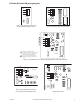
Proportional
N O T E
If multiple proportional valves are used on a single 4 to 20 mA loop, each valve must have
its own isolation transformer.
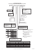
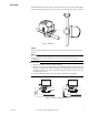
1. Remove the cover from the actuator, then connect the power and control wiring to the
terminal block (Figure-4 and Figure-5).
N O T E
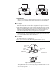
All units are shipped with the actuator in the direct-acting, 0 to 10 Vdc mode, which means
that the valve opens the B port upon receiving an increasing Vdc control signal. To change
the action to reverse-action (valve closes with an increase in control signal), simply remove
the action jumper J2 and relocate it to the reverse-acting pins. See Figure-4 and Figure-5.
2. Reinstall the cover onto the actuator.
INITIAL SETUP
Application Notes
These valves are designed for application to closed hydronic heating and cooling systems.
Use in systems which have substantial make-up water (open systems) is not recommended.
High levels of dissolved oxygen, chlorine, and debris that may be found in open systems can
attack the valve materials and result in premature failure.
3-Wire Floating "T" Type
The controller or thermostat used to operate the "T" type must be configured to turn off the
control signal after being on continuously for three minutes.
3-Wire Floating Time Out "T" Option
If the control system used does not have the ability to limit the running time, then the time
out option must be utilized, which automatically cuts off the control signal to the valve after
three minutes of continuous operation. This is standard on the spring return, and is an option
on the non-spring return.
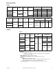
Proportional "P" Type
Multiple "P" valves may be connected to a single controller, up to the current rating of the
controller and transformer. For 4-20 mA control, a separate isolation transformer must be
used with each valve. The actuator is also provided with a jumper to allow the action to be
reversed. All units are shipped with the actuator in the DA (direct acting) mode, which means
that the valve opens the B port upon receiving an increasing control signal. To change the
action to reverse action (valve closes upon receiving an increasing control signal), simply
remove the action jumper and relocate it to the RA (reverse acting) pins.
CHECKOUT
1. Make sure the valve operates freely before installing the valve.
2. If the stem does not operate freely it may indicate that the stem was damaged and may
require that the valve be repaired or replaced.
3. After the piping is under pressure check the valve body and the connections for leaks.
4. After the valve and actuators are installed power the actuator and check the operation.
a. For two-way model:
Power the valve to the close position (per label), and the "B" port should be closed.
b. For three-way model:
Power the valve to the open position (per label), and the "A" port should be closed.
c. For Spring Return model:
Removing power should return the actuator to its normal position.