
User Guide

F-27013-4 © Copyright 2006 TAC All Rights Reserved. 9
4. Solder the valve body in place, directing the flame tip away from the valve and taking
care not to overheat the joint area. When finished, cool the valve quickly with a wet
cloth.
N O T E
The valve body may be submerged in water, or pressurized, for leak testing before
reattaching the actuator.
5. Reinstall the actuator according to "Reattaching the Actuator to the Valve Body."
NPT and Rp Threaded Valves
N O T E
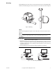
When installing threaded valves, the actuator should be detached from the valve body to
ease installation. To do so, first slowly move the actuator’s manual operating lever (on the
front of the actuator) to the middle position. Then latch the solenoid by placing the red
manual solenoid latch lever on the side of the actuator to the "Up" position. Finally detach
the actuator by depressing the release button and pulling the actuator away from the valve
body (Figure-9).
1. Apply teflon tape to all but the last two threads on the end of a properly threaded, reamed,
and cleaned pipe. Make sure that pipe chips, scale, etc. do not get into the pipe since this
material may lodge in the valve seat and prevent proper closing and opening of the valve.
2. Start the joint by hand-screwing the pipe to the valve. If the thread engages normally,
turn the pipe by hand as far as it will go.
3. Use a wrench to fully tighten the valve to the pipe using the flats located on the valve
body ports. Take care not to over-tighten or strip the threads.
4. Reinstall the actuator according to "Reattaching the Actuator to the Valve Body."
Reattaching the Actuator to the Valve Body
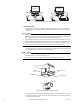
1. Before reinstalling the actuator, be sure that its manual operating lever is in the mid-
position, and that the solenoid is latched. The solenoid is latched when the manual
solenoid latch lever is in its "Up" position (Figure-9).
2. Depress the release button.
3. Align the valve body with the actuator to ensure the stem is inserted into the large mat-
ing hole on the bottom side of the actuator (Figure-9).
4. Engage the actuator on the body and release the button.
Wiring
N O T E
• Multiple actuators may be connected to a single controller, up to the current rating of the
controller and transformer. Do not exceed the maximum current draw of the controller.
• Use of a properly sized, inherently limited, Class 2 transformer is recommended.
• Use only 18 to 24 AWG copper wire for all connections.
• The return spring feature is primarily a safety feature. It is recommended that the spring
return feature is not used for routine, normal operation.
Three-wire Floating
N O T E
• The three-wire floating spring return valve includes a time-out feature that automatically
turns off the control signal to the valve after a pre-determined period of continuous oper-
ation. This time period is three minutes at 60 Hz and 3.6 minutes at 50 Hz.
• Spring return valves feature a two second time delay upon power loss, to prevent the loss
of valve position during brief outages. There is a three second delay at power-up.
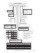
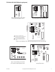
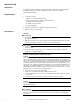
1. Remove the cover from the actuator, then connect the power and control wiring to the
terminal block (Figure-1 and Figure-3).
2. Reinstall the cover onto the actuator.