
Install Instructions

Printed in U.S.A. 2-10 © Copyright 2010 Schneider Electric All Rights Reserved. F-26801-8
SPECIFICATIONS
Inputs
Outputs
Electrical:
Stroke, 60 Hz: 2 minutes 30 seconds.
50 Hz: 3 minutes.
Action, T series: Direct acting. P series: Direct acting (Valve
opens B port with increase in signal). Field selectable
reverse acting.
Mechanical:
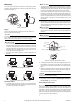
Manual Override, Allows manual positioning.
Operating Pressure Limits, 300 psi (2068.4 kPa) static
pressure.
Material:
Actuator: High temperature plastic.
Valve: Body: forged brass; Stem: chrome-plated brass;
Seat: brass; Plug/paddle: high temperature thermoplastic/
rubber.
Flow Characteristic, 1.0 to 4.0 Cv: Equal percentage. 7.0/
8.0 Cv: Linear.
Environment
Ambient Temperature Limits:
Shipping & Storage, -40 to 158°F (-40 to 70°C)
Operating, 35 to 125°F (1.7 to 52°C).
Fluid, 32 to 200°F (0° to 93°C) (not steam rated).
Humidity: 5 to 95% RH, non-condensing.
Seat Leakage: ANSI class IV (0.01%)
Shipping Weight: 1.9 lbs (860 g), actuator and valve body.
Location: NEMA Type 1.
Agency Listings:
UL 873: Underwriter Laboratories (File #E9429 Category
Temperature-Indicating and Regulating Equipment), Class 2.
CUL: UL Listed for use in Canada by Underwriters Laboratories.
Canadian Standards C22.2 No. 24.
European Community: EMC Directive (89/336/EEC)
Australia: This product meets requirements to bear the C-Tick
Mark according to the terms specified by the
Communications Authority under the Radiocommunications
Act 1992.
INSTALLATION
Inspection
Inspect package for damage. If damaged, notify the appropriate
carrier immediately. If undamaged, open package and inspect the
device for obvious damage.
Return damaged products.
Requirements•
• Tools (not provided):
— Wrench 1 to 1-5/8" (if threaded valve)
— Soldering equipment (if sweat fit)
— Pipe wrench according to pipe size (if threaded)
— #1 Phillips head screw driver
— Volt-ohm multimeter
• Training: Installer must be a qualified, experienced technician
• Other accessories as appropriate
Precautions•
• Electrical shock hazard! Disconnect power before installation to
prevent electrical shock or equipment damage.
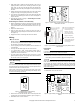
• Make all connections in accordance with the electrical wiring dia-
gram and in accordance with national and local electrical codes.
Use copper conductors only.
C A U T I O N
• Avoid locations where excessive moisture, corrosive fumes,
explosive vapors, or vibration are present.
• Avoid electrical noise interference. Do not install near large con-
ductors, electrical machinery, or welding equipment.
Floating Actuator
Control Circuit,
Max.
Total Actuator,
Max.
Powerup
Inrush
a
a
Transformer must be sized for Powerup Inrush.
Running
Series Action Vac mA VA VA VA
AT13A00T
Spring
Return
24 Vac
+25%/-15%
50/60 Hz
24 0.6
10
1.9
AT23A00T 24 0.6 1.9
AT33A000
Non-
spring
Return
——1.01.0
AT33A00T — — 1.2 1.2
Proportional Actuator
Control
Circuit, Max.
Total Actuator, Max.
Powerup
Inrush
a
a
Transformer must be sized for Powerup Inrush.
Running
Series Action VAC Range (Rin) VA VA
AP13A000
Spring
Return
24 Vac
+25%/-
15%
50/60 Hz
b
0-10Vdc
(>200K)or
0-5Vdc
(>200K) or
5-10 Vdc
(>200K) or
4-20 mA
(300)
b
Factory supplied. Actual Range is 1-9 Vdc.
10
1.7
AP23A000
AP33A000
Non-
spring
Return
1.7
Spring Return Non-Spring Return
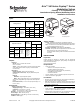
Erie™ VM Series Poptop™ Series
Modulating Valves
Floating "T" & Proportional "P"
Standard and Spring Return Modulating Valves
Installation Instructions