
Install Instructions

On October 1st, 2009, TAC became the Buildings business of its parent company Schneider Electric. This document reflects the visual identity of Schneider
Electric, however there remains references to TAC as a corporate brand in the body copy. As each document is updated, the body copy will be changed to reflect
appropriate corporate brand changes.
Schneider Electric
1354 Clifford Avenue
P.O. Box 2940
Loves Park, IL 61132-2940
www.schneider-electric.com/buildings
Copyright 2010, Schneider Electric
All brand names, trademarks and registered
trademarks are the property of their respective
owners. Information contained within this document
is subject to change without notice.
F-26801-8
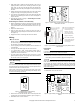
Figure-9 Typical Wiring of 3-Wire Proportional Spring Return
Valves
Application Notes
The valves are designed for application to closed hydronic heating
and cooling systems. Use in systems which have substantial make-
up water (open systems) is not recommended. High levels of
dissolved oxygen, chlorine, and debris that may be found in open
systems can attack the valve materials and result in premature
failure.
Three-Wire Floating “T” Type Actuator
The controller or thermostat used to operate the three-Wire floating
actuator must be configured to turn off the control signal after being
on continuously for three minutes.
Three-Wire Floating Time-out “T” Type Actuator
If the control system does not have the ability to limit the running time,
then the time-out option must be utilized. This automatically cuts off
the control signal to the valve after three minutes of continuous
operation. This is standard on the spring return actuator, and is an
option on the non-spring return actuator.
Proportional “P” Type Actuator
Multiple proportional valves may be connected to a single controller
up to the current rating of the controller and transformer. For 4 to
20mA control, a separate isolation transformer must be used with
each valve. The actuator is also provided with a jumper to allow the
action to be reversed. All units are shipped with the actuator in the
DA (direct acting) mode. This means the valve opens the B port upon
receiving an increasing control signal. To change the action to
reverse acting (valve closes upon receiving an increasing control
signal), simply remove the action jumper and relocate it to the RA
(reverse acting) pins.
CHECKOUT
1. Make sure the valve operates freely before installing the valve.
2. If the stem does not operate freely, it may indicate that the stem
was damaged and may require that the valve be repaired or
replaced.
3. After the piping is under pressure, check the valve body and the
connections for leaks.
4. After the valve and actuators are installed, power the actuator
and check operation.
• Two-way Model:
Power the valve to the close position (per label), and the “B”
port should be closed.
• Three-way model
Power the valve to the open position (per label) and the “A”
port should be closed.
THEORY OF OPERATION
The PopTop Series floating or proportional valves are modulating
valve actuator assemblies. The modulating valves are designed to
control the flow in the circuit by making incremental adjustments to
the flow path within the valve.
The spring return PopTop Series modulating valves, when powered,
move the actuator to the desired position, at the same time tensing
the spring return system. When power is removed for more than two
seconds, the spring returns the actuator to the normal position.
MAINTENANCE
The modulating PopTop Series valves require no maintenance.
Regular maintenance of the total system is recommended to assure
sustained, optimum performance.
FIELD REPAIR
Replace any damaged or failed components with complete body or
actuator replacements.
24 Vac
COM
DC IN
100-517
J2