
Install Instructions

F-26801-8 © Copyright 2010 Schneider Electric All Rights Reserved. 3
1. Apply Teflon tape to all but the last two threads on the end of a
properly threaded, reamed, and cleaned pipe. Make sure pipe
chips, scale, etc. do not get into the pipe since this material may
lodge in the valve seat and prevent proper closing and opening of
the valve.
2. Start the joint by hand-screwing the pipe to the valve. If the thread
engages normally, turn the pipe by hand as far as it will go.
3. Use a wrench to fully tighten the valve to the pipe using the flats
located on the valve body ports. Take care not to over-tighten or
strip the threads.
4. Re-install the actuator according to "Reattaching the Actuator
to the Valve Body" below.
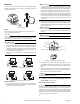
Reattaching the Actuator to the Valve Body
1. Before reinstalling the actuator, be sure that its manual operating
lever is in mid-position, and that the solenoid is latched. The sole-
noid is latched when the manual solenoid latch lever is in its “Up”
position.
2. Depress the release button.
3. Align the valve body with the actuator to ensure the stem is
inserted into the large mating hole on the bottom side of the actu-
ator (Figure-4).
4. Engage the actuator on the body and release the button.
Wiring
C A U T I O N
• Multiple actuators may be connected to a single controller up to
the current rating of the controller and transformer. Do not exceed
the maximum current draw of the controller.
• Use of a properly sized, inherently limited, Class 2 transformer is
recommended.
• Use only 18 to 24 AWG copper wire for all connections.
• If a conduit fitting is used, remove plastic bushing prior to
installation and use two nuts to prevent fitting from pushing
against the actuator circuit board.
• The return spring feature allows the valve to return to a normal
position upon loss of power. The spring return feature should not
be used for routine, normal operation.
Three-Wire Floating
N O T E
The three-wire floating spring return valve includes a time-out feature
that automatically turns off the control signal to the valve after a pre-
determined period of continuous operation. This time period is three
minutes at 60 Hz and 3.6 minutes at 50 Hz.
Spring return valves feature a two second time delay upon power
loss to prevent the loss of valve position during brief outages. There
is a three second delay at power-up.
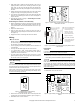
Figure-5 Typical Wiring of 3-Wire Floating
Non-Spring Return Actuator
1. Remove the cover from the actuator, then connect the power and
control wiring to the terminal block (Figure-5, Figure-6, Figure-7).
2. Reinstall the cover onto the actuator.
Figure-6 Typical Wiring of 3-Wire Floating Non-Spring Return
Valves with Time-Out
Figure-7 Typical Wiring of 3-Wire Floating Spring Return Valves
with Time-Out
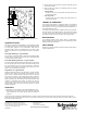
Proportional
N O T E
If multiple proportional valves are used on a single 4 to 20 mA loop,
each valve must have its own isolation transformer
1. Remove the cover from the actuator, then connect the power and
control wiring to the terminal block (Figure-8 and Figure-9).
N O T E
All units are shipped with the actuator in the direct-acting 0 to 10 Vdc
mode, which means that the valve opens the B port upon receiving
an increasing Vdc signal. To change the action to reverse-acting
(valve closes with an increase in control signal), simply remove the
action jumper J2 and relocate it to the reverse-acting pins. See
Figure-8 and Figure-9.
2. Reinstall the cover onto the actuator.
Figure-8 Typical Wiring of 3-Wire Proportional Non-Spring Return
Valves
J2
C1
+
+
R1
C
2
J1
A
COM
OPEN
14-28 AWG
CLOSE
COM
OPEN
CLOSE
100
-
315
CLOSE
COM
OPEN
100-31
6
1
2
2
1
2
The 24 Vac/COM supply
must be maintained
continuously for valve
operation. The valve
returns to its normal
position whenever this
supply is interrupted.
The CLOSE and OPEN
control signals share the
COM terminal with the
24 Vac supply.
24 Vac
Close
COM
Open
J2
J3
1
100
-
516
24 Vac
COM
DC IN
J1
J2
J3
1
00-317