
Install Instructions

2 © Copyright 2010 Schneider Electric All Rights Reserved. F-26801-8
Mounting
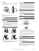
The valves can be mounted in horizontal or vertical piping. When
installed in horizontal piping, the actuator must be above the valve
body. Refer to Figure-1.
Piping
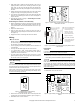
Refer to the piping diagrams in Figure-2 for two-way valves. For
three-way valves refer to Figure-3.
N O T E
The 3-way is only configured as B port normally closed. For normally
open configuration to the coil turn valve around. For proportional
valves, set the control action (direct or reverse) accordingly.
C A U T I O N
• The valve should be used in a closed loop system.
• All valves must be piped so the plug closes against the direction
of flow. For two-way valves, flow is from port B to port A. For
normally closed three-way valves, B is the service port and A is
the bypass port. For normally open three-way valves. A is the
service port and B is the bypass port.
• Three-way valves must be piped in a mixing configuration, not
diverting.
Figure-2 Two-Way Spring Return Valves
Figure-3 Three-Way Spring Return Valves
Sweat End Valves
1. To manually open the valve so the plug is not in contact with the
valve body, slowly position the actuator’s manual operating lever
(on front of the actuator) to mid-position.
C A U T I O N
• The plug inside the valve is made of a plastic material. It may be
damaged by heat conducted through the valve body if it remains
seated against its port during soldering. Be sure to manually open
the valve to mid-position before soldering to prevent damage.
• If the manual operating lever does not move freely for manual
positioning, the solenoid may have latched during shipping. Do
not force the lever. Instead, first unlatch the solenoid by placing
the red manual solenoid lever (on the side of the actuator) in the
“Down” position, then place the manual operating lever in the
mid-position
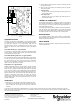
2. With the valve in mid-position, latch the solenoid by placing the
manual solenoid latch lever in the “Up” position. Detach the actu-
ator by depressing the release button and pulling it away from the
valve body (Figure-4).
C A U T I O N
• To avoid damage to the actuator and to ease the soldering pro-
cess, be sure to remove the actuator from the valve body before
soldering.
C A U T I O N
• Use only solder with a melting point below 600°F (315°C).
Figure-4 Three-Way Spring Return Valves
3. Thoroughly clean the ends of the water supply tubing for a mini-
mum distance of 1 inch (25 mm) from the end, so a good joint can
be made in the shortest time and without an excessively large
flame.
4. Solder the valve body in place, directing the flame tip away from
the valve and taking care not to overheat the joint area. When fin-
ished, cool the valve quickly with a wet cloth.
N O T E
The valve body may be submerged in water, or pressurized for leak
testing before reattaching the actuator.
5. Reinstall the actuator according to "Reattaching the Actuator to
the Valve Body" on the next page.
NPT and Rp Threaded Valve
N O T E
When installing threaded valves, the actuator should be detached
from the valve body to ease installation. To do so, first slowly move
the actuator’s manual operating lever (on the front of the actuator) to
mid-position. Latch the solenoid by placing the red manual solenoid
latch lever on the side of the actuator to the “Up” position. Finally,
detach the actuator by depressing the release button and pulling the
actuator away from the valve (Figure-4).
85
360
Figure-1 Mounting.
Power/Signal
Spring Return
Normally Closed
COIL
A
B
Power/Signal
Spring Return
Normally Open
COIL
AB
Power/Signal
Normally Closed
COIL
A
B
Power/Signal
Normally Open
COIL
A
B
Release
Button
Stem Mating Hole
Stem
Pin
Pin Mating Hole
Solenoid Latch
Lever
Manual Opening
Lever