
Install Instructions
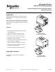
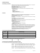
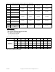
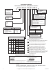
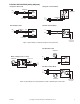
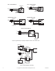
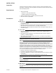
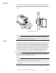
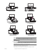
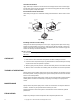
Table Of Contents
- Application
- Features
- SPECIFICATIONS
- Service
- System Static Pressure Limits
- Close-off
- Fluid/Ambient Temperature Limits
- S eat Leakage
- Voltage
- Power Requirements
- End Switch
- Control Signal
- Timing, Full Open to Full Close
- Materials
- Ambient Temperature Limits:
- Humidity
- Agency Listings
- Shipping Weight (Actuator/Valve Assembly)
- Table-1 Valve Body and Actuators Model Chart
- Table-2 Flow Coefficients & Maximum Close-Off Pressure Differential
- Table-3 Water Valve Sizing Table*
- TYPICAL APPLICATION (wiring diagram)
- INSTALLATION
- . Electrical shock hazard! Disconnect power before installation to prevent electrical shock or equipment damage.
- . Avoid locations where excessive moisture, corrosive fumes, explosive vapors, or vibration are present.
- . When making lead connections within the actuator, use caution not to put leads or connectors below the motor.
- This is a class B (European Classification) product. In a domestic environment this product may cause radio interference in which case the user may be required to take adequate measures.
- Use in systems which have substantial make-up water (open systems) is not recommended. Follow proper water treatment practices and system procedures. Refer to document F-26080-1 for Water and Steam EN205 Guidelines.
- Do not solder with actuator in place, or with paddle against seat, as the heat can damage the unit. Before soldering, move the manual open lever into Open position then remove the actuator from the body. Orient paddle so it is not against a seat.
- Do not use the valve body to manually open the actuator as damage to the valve actuator will result.
- CHECKOUT
- 1. Make sure the valve stem rotates freely before and after installing the actuator.
- 2. If the stem does not operate freely it may indicate that the stem was damaged and may require that the valve be repaired or replaced.
- 3. After the piping is under pressure, check the valve body and the connections for leaks.
- 4. After the valve and actuator are installed, power the actuator and check the operation.
- THEORY OF OPERATION
- MAINTENANCE
- FIELD REPAIR
- DIMENSIONAL DATA

6 Copyright 2010 Schneider Electric All Rights Reserved. F-26496-7
To Aux. Circuit
Motor
THERMOSTAT
THERMOSTAT
L1
(HOT)
L2
Flair - Terminal Block
1 4 5
2
3
To Aux. Circuit
Motor
THERMOSTAT
THERMOSTAT
L1
(HOT)
L2
Taco - Terminal Block
1
2
3
TAC Erie Wire LeadsTAC Erie Wire Leads
TAC Erie Terminal Block
Motor
End SwitchRed
To Aux. Circuit
Red
Black
Black
L1
(HOT)
L2
Motor
End SwitchRed
To Aux. Circuit
Red
Black
Black
L1
(HOT)
L2
To Aux. Circuit
24 V 5A max
THERMOSTAT
L1
(HOT)
L2
Motor
TR
ES ES
TH
End Switch
TR
TH
Figure-3 Typical Wiring of a PopTop to Replace a Flair or Taco 3-Wire Valve
Thermostat
T1
T2
Valve #1
Valve #2
BURNER
CONTROL
TH
TR
ES
ES
TH/TR
T
T
L1
L2
TH
TR
ES
ES
TH/TR
Figure-4 Typical Multiple Valve Wiring