RX8320 ATSC Broadcast Receiver Software Version 4.3.
RX8320 ATSC Broadcast Receiver Copyright © Copyright Ericsson AB 2011. All rights reserved. Disclaimer No part of this document may be reproduced in any form without the written permission of the copyright owner. The contents of this document are subject to revision without notice due to continued progress in methodology, design and manufacturing. Ericsson shall have no liability for any error or damage of any kind resulting from the use of this document.
Contents Contents 1 1.1 1.2 1.3 Introduction............................................................................................ 5 Who Should Use this User Guide? .......................................................... 5 What Equipment is Covered by this User Guide? ................................... 5 Hardware and Software Options ............................................................. 5 2 2.1 2.2 2.3 2.4 2.5 Installing the Equipment ...................................................
Contents List of Figures Figure 1 Figure 2 Figure 3 Figure 4 Figure 5 Figure 6 Figure 7 Figure 8 Figure 9 Figure 10 Figure 11 Figure 12 Figure 13 Figure 14 Figure 15 Figure 16 Figure 17 Figure 18 Figure 19 Rear Panel Connectors ............................................................................8 Front Panel LEDs and Pushbuttons .......................................................14 Front Panel Menus .................................................................................
Introduction 1 Introduction 1.1 Who Should Use this User Guide? This User Guide is written for operators/users of the RX8320 ATSC Broadcast Receiver to assist in installation and operation. Detailed information can be found in the Reference Guide companion document which is issued on CD. Warning! Do not remove the covers of this equipment. Hazardous voltages are present within this equipment and may be exposed if the covers are removed.
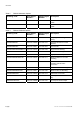
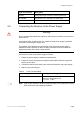
Introduction Table 2 RX8320 Hardware Options Marketing Code Price Object Number Supply Object Number Description RX8XXX/CABLE/XLR FAZ 101 0108/24 RPM 901 364 XLR Terminal Audio Break-out Cable RX8XXX/CABLE/SCRTRM FAZ 101 0108/23 RPM 901 365 Screw Terminal Audio Break-out Cable Table 3 RX8320 Software Options Marketing Code Price Object Number Supply Object Number Description RX83XX/SWO/AC3 FAZ 101 0108/28 FAT 102 0107 Dolby Digital® Decoding / Downmixing RX83XX/SWO/PW FAZ 101 0108/
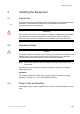
Installing the Equipment 2 Installing the Equipment 2.1 Introduction For best performance and reliability follow the instructions for site requirements and installation in the Reference Guide and only use installation accessories recommended by the manufacturers. Warning! Do not remove the covers of this equipment. Hazardous voltages are present within this equipment and may be exposed if the covers are removed.
Installing the Equipment Warning! The Technical Earth is not a Protective earth for electric shock protection. This unit must be correctly earthed through the molded plug supplied. If the local mains supply does not have an earth conductor do not connect the unit. Contact Customer Services for advice. Before connecting the unit to the supply, check the supply requirements in Annex B of the Reference Guide. 2.
Installing the Equipment 2.5 Type of Connector Description ALARM 9-way male D-type connector for alarm signal output. AC POWER IEC100-120 V AC / 220-240 V AC power input. TECHNICAL EARTH Spade connector for unit technical earth. Connecting the Receiver to the Power Supply Warning! Do not overload wall outlets and extension cords as this can result in a risk of fire or electric shock.
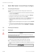
Quick Start Guide: Connect-Power-Configure 3 Quick Start Guide: Connect-Power-Configure 3.1 Connecting the Receiver The following points should be noted when making signal connections to the receiver: • If you have an incoming 8VSB feed, this should be connected to the rear panel connector marked RF INPUT. • If you have an incoming ASI feed, this should be connected to the ASI Input. • Decoded PAL or NTSC video is output on connector CVBS.
Quick Start Guide: Connect-Power-Configure 4. During initialization, confirm that the Status LED is on and all Up, Down, Left, Right, Edit and Save pushbuttons are lit. 3.2.2 Power Up Operating Modes When the equipment is switched on it will assume the control mode that was set when the power was turned off. 3.3 Configuring the Inputs 3.3.1 Transport Stream (ASI) Input To configure the unit for ASI input: 1. Select ASI input from sub-menu 2.1Select Input. 3.3.
Quick Start Guide: Connect-Power-Configure 3.6 • The unit will automatically decode the first video component that it finds within the selected service. • An alternative video component may be selected from the service tab on the Web Control interface. • If the incoming video is successfully decoded then the status OK should be displayed on the appropriate page. • Successfully decoded High Definition video will be output from the connector marked Video Component.
Quick Start Guide: Connect-Power-Configure and Maximum CAM Components Per Service dialog boxes. The user should refer to the CAM vendor for CAM compatibilities before setting this up. • This list may be modified from the CA tab on the Web Control interface. Note: This is only applicable for units/models that have Multi-service Decryption licenses enabled.
Front Panel Control 4 Front Panel Control 4.1 Introduction The Front Panel display and keypad may be used to configure, control and monitor the receiver when an external control system is not used. Note: 4.2 A list of receiver user settings that may be viewed or changed via the front panel and those that may be viewed or changed via the external web browser interface can be found in the Reference Guide.
Front Panel Control 4.3.2 LCD A 2-line x 40-character back-lit dot-matrix Liquid Crystal Display (LCD) displays various menus and settings. The menus and setting available will vary depending on which options have been enabled through the purchase of a suitable license. 4.3.3 Arrow Pushbuttons Four arrow pushbuttons (or keys) are used to navigate through the front panel LCD menus.
Front Panel Control 4.4 Front Panel Menus An overview of the available Front Panel menus is shown below. The menus and settings available will vary depending on which receiver model is being used and which options have been enabled through the purchase of a suitable license. Note: The menu structure is subject to change as further functionality is added. SWITCH ON 1.1 Network Menu Boot Screen INITIALIZING 4.3.2 (Bank 0) 1. System Menu — — — — — 1.1 1.2 1.3 1.4 1.
Front Panel Control 4.4.1 Menu Structure The Front Panel menus and sub-menus, available on the LCD, provide the configuration parameters that may be viewed, selected and/or modified. • • • • System - Provides sub-menus for viewing/configuring the receiver hardware and access parameters. - Network – Enables the input and display of the addresses required to communicate with the receiver. Access to the receiver Status page is also available from this sub-menu.
Front Panel Control • • Output Menu - Provides sub-menus for viewing/configuring the receiver output parameters. - Output Selection - Enables selection of the required output type. - TS Feed Selection - Enables selection of the descrambling for the Transport Stream Feed. Presets - Provides sub-menus for viewing, storing and retrieving up to 40 sets of input configuration parameters (tuning parameters and service selections). - Preset State - Enables the current list of presets to be viewed.
Web Browser Control 5 Web Browser Control 5.1 Introduction A personal computer (PC) running a Web Browser can be used to configure, control and monitor the receiver remotely. The following web browsers have been tested: 5.1.1 • Microsoft Internet Explorer (This is the only browser supported by Ericsson) • Mozilla Firefox (Functional but unsupported) • Google Chrome (Functional but unsupported) Setting Up Web Browser Remote Control 1.
Web Browser Control Unit Model Number and Name About button Header Function Tabs Navigation Path Toolbar Main Web Page Results Frame Figure 4 • Web Page Overview (Typical) Header – The header of the web page displays the Ericsson logo and the unit model number name. At the right-hand side of the header an About button which, when clicked, displays an information dialog about the unit, including the software version number. Click the OK button to close the dialog.
Web Browser Control web page. When you switch between tabs, the browser remembers the path for each tab. • Navigation Path – The web pages are organized into a tree-like structure, like the directory on a computer. The current complete navigation path is always displayed at the top of the web page, which shows the route taken to the currently displayed web page.
Web Browser Control 5.3 Web Pages 5.3.1 Status This web page shows a number of top-level parameters indicating the current status of the receiver. Figure 6 5.3.2 Status Web Page Device Info The Device Info web page provides access to system-level settings for the receiver and can be used to enable the Front Panel Lockout Facility and initiate Rebooting functions.
Web Browser Control Figure 7 Device Info Web Page This page also provides buttons to the following further web pages: • Build – provides details of equipment build and version numbers. No usereditable fields. • Environment – provides details of the physical environment of the equipment such as temperature and fan speed. No user-editable fields. • Network Settings – provides details of settings for control 1 and 2 networks. No user-editable fields.
Web Browser Control 5.3.3 Alarms The Alarms web page provides access to the alarms settings for the receiver. The contents of this page are composed mainly of fields with drop-down menus which allow the setting or masking of various alarms and check boxes which can be used to activate relay mapping. Two of the alarm fields, namely C/N (Carrier-to-Noise) Margin and Over Temperature also have associated entry fields which allow the user to enter a value which, if exceeded, will activate the alarm.
Web Browser Control Figure 8 5.3.4 Alarms Web Page Customization Web Page The Customization web page provides access to the list of licenses enabled on the equipment and to enable further licenses (as purchased) by entering the custom key provided. Figure 9 5.3.
Web Browser Control Figure 10 CA Web Page 5.3.6 Input The Input Web Page provides access to the parameters of the various inputs to the receiver. The page, which is displayed, depends on which Input card is fitted. The options are: • 8-VSB Input Card Typically the pages include parameters for input feed lock status and bit rate, primary and secondary feed selection, input tuning, input signal and quality levels.
Web Browser Control Figure 11 5.3.7 Input Web Page (8VSB Input Card fitted) Service Plus The Service Plus web page provides access to the various encryption and encoding services available to the receiver. A Service Control table is displayed showing which services are available. The only user-editable fields in this table are the Decrypt and Decode checkboxes. The user can select Decrypt, Decode, Filter or Remap for each service, depending on the node selected on the Output tab.
Web Browser Control • Splice - gives access to the splice operation parameters. • DVB Subtitles - gives access to the Digital Video Broadcasting (DVB) subtitles parameters. • Teletext - gives access to the Teletext parameters.
Web Browser Control 5.3.9 Output The Output web page provides access to the output feed parameters of the receiver. Figure 14 Output Web Page 5.3.10 Download The Download web page provides access to the over air download status of the receiver. There are no user-editable fields on this page.
Web Browser Control Figure 15 Download Web Page 5.3.11 SNMP This page gives access to the Simple Network Management Protocol (SNMP) parameters for the receiver, including protocol selection and MIB parameters. Figure 16 SNMP Web Page 5.3.12 Presets The Presets web page gives access to a list of 40 preset configurations. This feature may be used to store input (tuning) parameters and service selection (service id only) in order that settings do not have to be re-entered when changes are made.
Web Browser Control Figure 17 Presets Web Page 5.3.13 Save/Load The Save/Load web page provides a range of configuration download and upload facilities, including saving and restoring unit configuration, saving unit MIB files, saving alarm log files and saving splice log files.
Web Browser Control Figure 18 Save/Load Web Page 5.3.14 Help The Help web page gives access to a Web Interface User Guide which provides a brief description of the interface functionality.
Equipment Packaging 6 Equipment Packaging 6.1 Packaging Statement The outer carton and any cardboard inserts are made from 82% recycled material and are fully recyclable. The Stratocell® or Ethafoam 220® polyethylene foam inserts can be easily recycled with other low density polyethylene (LDPE) materials 6.2 Packaging Markings The symbols printed on the outer carton are described below: Handle with care. This way up. Fragile. Protect from moisture.
Materials Declarations 7 Materials Declarations 7.1 Overview Ericsson products are designed and manufactured in keeping with good environmental practice. Our component and materials selection policy prohibits the use of a range of potentially hazardous materials. In addition, we comply with relevant environmental legislation. 7.2 For the European Union For product sold into the EU after 1st July 2006, we comply with the EU RoHS Directive. We also comply with the WEEE Directive. 7.
Disposal of this Equipment 8 Disposal of this Equipment 8.1 General Dispose of this equipment safely at the end of its life. Local codes and/or environmental restrictions may affect its disposal. Regulations, policies and/or environmental restrictions differ throughout the world. Contact your local jurisdiction or local authority for specific advice on disposal. 8.
Recycling 9 Recycling Ericsson SA TV Recycling has a process facility that enables customers to return Old and End-of-Life Products for recycling if it is required. Ericsson provides assistance to customers and recyclers through our Ericsson and SATV Recycling eBusiness Portal. This can be reached at: https://ebusiness.ericsson.net/. To gain access to the Recycling site, you must be set up with a unique login and password. To request the login, please contact tvtechpubs@ericsson.