
Operating instructions
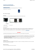


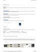


Location of the Ethernet and Single AC Connectors at the Rear Panel
All signal connections are made via the rear panel.
NOTE : Single A.C. PSU version shown.
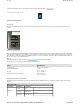
Front Panel
Identifying Items Located at the Front Panel
The front panel provides a 2 line by 40 character display, 6 buttons, and a red/amber/green tri-colour status LED.
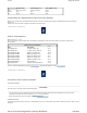
Items on the Front Panel
LCD
Control and status information is displayed on a 2 line by 40 character display.
Buttons
Six buttons are provided for navigating through the front panel menus. See Front Panel Controls and Pushbuttons for more details.
Status LED
An LED located at the front panel gives an indication of the status of the unit.
USB Connector
This is not for customer use. Please refer to USB connector.
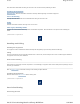
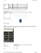
1 ‘RU’ Base Chassis Dual PSU Rear Panel
This chassis is the same as the 1 ‘RU’ Base Chassis but with the dual PSU.
Data Ethernet
Control Ethernet AC Input
Location of the Ethernet and Dual AC Connectors at the Rear Panel (Blanking Plates Fitted)
Control Ethernet AC Input
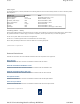
LED State Unit Status
Off Unit not powered
Green No active warnings or alarms
Amber Active warning/s, minor or major alarm/s
Red Active critical alarm/s
Page
38
of
153
Cover
9/11/2012
file://C:\Users\ebriacl\AppData\Local\Temp\~hh7DF.htm