Cover Page 1 of 153 1553-FGC 101 1010 Uen A Video Processor HANDBOOK VP/CHASSIS/1AC, VP/CHASSIS/2AC and Options Software Version 1.9.0 (and later) © Ericsson AB 2011. All rights reserved Preliminary Information Scope of This Information This topic defines who should use this information, and what equipment and options are covered. About This Information Tabulates the history of this information. Lists the templates and style sheets used to create the file.
Cover Page 2 of 153 Scope of This Information Who Should Use this Handbook This guide is written for operators and users of the Video Processor and describes its functions and operation. It will assist in the installation and day-to-day care and operation of the unit. Maintenance information that requires covers to be removed is not included. WARNING! Do not remove the covers of this equipment. Hazardous voltages are present within this equipment and may be exposed if the covers are removed.
Cover Page 3 of 153 VP/HWO/EN8180/ENC EN8180 MPEG-2 HD Encoder Module See Introduction>Option Cards>EN8180 HD MPEG-2 VCM VP/HWO/ASI/2IN2OUT ASI I/O Module See Introduction>Option Cards>ASI Option Module VP/HWO/EXTSYNC Video Processor External Sync Module See Introduction>Option Cards>External Sync Input VP/CAB/BAL D-Type to balanced XLR breakout cable See Installing the Equipment>External Interfaces> VCM>Audio Input VP/CAB/UNBAL D-Type to unbalanced XLR breakout cable See Installing the Equipme
Cover Page 4 of 153 Disclaimer The contents of this document are subject to revision without notice due to continued progress in methodology, design and manufacturing. Ericsson AB shall have no liability for any error or damage of any kind resulting from the use of this document. Registered Trademarks Dolby® is a registered trademark of Dolby Laboratories Licensing Corporation. DTS® is a registered trademark of Digital Theater Systems, Inc Ethernet® is a registered trademark of Xerox Corporation.
Cover Page 5 of 153 Contact Information Ericsson Customer Services Support Services Our primary objective is to provide first class customer care that is tailored to your specific business and operational requirements. All levels are supported by one or more service performance reviews to ensure the perfect partnership between Ericsson and your business. Warranty All Ericsson Products and Systems are designed and built to the highest standards and are covered under a comprehensive 12 month warranty.
Cover Page 6 of 153 Technical Training Training Courses Ericsson provides a wide range of training courses on the operation and maintenance of our products and on their supporting technologies. We can provide both regularly scheduled courses and training tailored to individual needs. Courses can be run either at your premises or at one of our dedicated training facilities.
Cover Page 7 of 153 Mechanical Support Do not use this product as a support for any other equipment. Web Browser access This product is designed to support control through Web browser access. The only supported browser is Microsoft IE8 (earlier versions of IE are not supported) © Ericsson AB 2011. All rights reserved Introduction The Unit is a flexible platform consisting of a base unit or chassis in to which various option cards can be plugged.
Cover Page 8 of 153 License Keys control the availability of some features and are issued to a specific base unit not an option card, even if the functionality being enabled is provided by an option card. Features License Keys consist of a feature, and the number of instances of this feature that are allowed within the chassis. License Keys are allocated on a ‘first configured first served’ basis within the chassis.
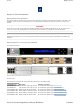
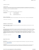
Cover Page 9 of 153 Video Processor Rear Panel - Single AC Chassis (EN8100 SD MPEG-2 VCMs fitted) Video Processor Rear Panel - Dual AC Chassis NOTE: Refer to Installing the Equipment > External Interfaces > Base Chassis for more details of the items at the rear and front panels. VP/CHASSIS/1AC 1U Base Chassis (AC) Describes the single AC power supply base chassis. VP/CHASSIS/2AC 1U Base Chassis (Dual AC) Describes the dual AC power supply base chassis. © Ericsson AB 2011.
Cover Page 10 of 153 Rear Panel The option cards, control Ethernet ports, data Ethernet ports, and the AC power input are all accessible at the rear of the base chassis. VP/CHASSIS/1AC Rear Panel Items [Single AC Chassis] Ethernet Port Numbering © Ericsson AB 2011. All rights reserved VP/CHASSIS/2AC 1U Base Chassis (Dual AC) Overview The Video Processor consists of a base chassis, dual AC inputs and up to four option cards.
Cover Page 11 of 153 Front Panel VP/CHASSIS/2AC Front Panel Items LCD Control and status information is displayed on a 2 line by 40 character display. Buttons Six buttons are provided for navigating through the front panel menus. Status LED The status LED is green when there are no active alarms or warnings and red if there is a critical alarm. The status LED is amber if there is an active warning, minor or major alarm. USB Connector This is not for customer use.
Cover Page 12 of 153 Option Cards Option Card Combinations Describes the supported combinations of option cards, maximum number of cards and recommended slot location for each option card. The following are the option cards supported in this release: EN7100 SD MPEG-2 VCM (VP/HWO/EN7100/ENC) This card can compress a standard definition video input using MPEG-2 encoding, and can compress up to eight channel pairs of audio depending on audio encoding mode.
Cover Page 13 of 153 HD H.264 VCM Note: If 2 x EN8190 fitted then the only other modules that may be fitted are the ASI IO module or the External Sync module. EN8100 6 4 Any slot 6 4 Any slot 6 4 Any slot HD MPEG-2 VCM 6 4 Any slot ASI IO Module 6 4 Slot 1 or slot 6 External SYNC Module 1 1 Any slot SD MPEG-2 VCM EN7100 SD MPEG-2 VCM EN8130 SD H.
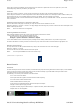
Cover Page 14 of 153 Summary of Features Overview The EN7100 SD MPEG-2 Video Compression Module (VCM) option card can encode a single standard definition video input using the MPEG-2 algorithm. EN7100 SD MPEG-2 VCM Rear Panel Inputs The card provides an SDI video input via a BNC connector, and digital audio input via a 15-way D-type connector. SDI Input via a 75 Ω BNC female connector.
Cover Page 15 of 153 © Ericsson AB 2011. All rights reserved SD MPEG-2 Video Encoding Inputs SDI Input via 75 ohm BNC connector. Digital Audio Input via 15 way D-Type connector Overview The SD MPEG-2 VCM can encode one standard definition video input. It can also encode up to eight channel pairs of audio (with appropriate licences), or pass through pre-encoded Dolby Digital encoded audio.
Cover Page 16 of 153 See also Technical Specification > SD MPEG-2 VCM > Video > Impairment Reduction. © Ericsson AB 2011. All rights reserved Audio Encoding Overview Up to eight channel pairs can be de-embedded from the HD-SDI or SDI video input, or up to four channel pairs can come via the 15 way D-Type Audio Input connector on the cards rear panel as either balanced or unbalanced AES/EBU digital audio.
Cover Page 17 of 153 HD-SDI Input Audio can be embedded on a serial digital interface (HD-SDI) feed within four groups. Each group contains two pairs. Hence each HD-SDI can carry up to a maximum of 2 x 4 = 8 pairs, or 16 mono channels. Each group has an associated Data Identifier (DID). The DIDs are set to the SMPTE 299M defaults for audio group 1 to group 4: Group 1 = 0x2E7 Group 2 = 0x1E6 Group 3 = 0x1E5 Group 4 = 0x2E4 The DIDs are located in ancillary packets in the data stream.
Cover Page 18 of 153 been purchased Dolby Digital pass through (Dolby Digital AC-3) Glitch suppression is supported in this mode 8 Dolby Digital Plus pass through Glitch suppression is supported in this mode 8 DolbyE pass through Compliant with SMPTE 302M 8 LPCM pass through Compliant with SMPTE 302M 8 Glitch Suppression Mode When in Dolby Digital pass through mode, the coding module monitors the encoded bitstream and if the framing structure is incorrect, a valid silence frame or the last goo
Cover Page 19 of 153 Timing The VCM aligns VBI data and compressed video frames within the bounds dictated by time stamping of received data, i.e. stamp the same PTS on the video and VBI that came in on the same frame. © Ericsson AB 2011. All rights reserved EN8100 SD MPEG-2 VCM Module The EN8100 SD MPEG-2 VCM (HWO/EN8100/ENC) has a unique processing engine that extracts the maximum efficiency possible from the MPEG-2 specification.
Cover Page 20 of 153 Video SDI video input. Frame re-synchronization. Programmable bandwidth filter. Adaptive spatial and temporal noise reduction (software option VP/SWO/SDMP2/NR) MPEG-2 MP@HL Video Encoding (0.5 to 54 Mbps) Vertical resolution: 576 or 288 (PAL), 480 or 240 (NTSC) Horizontal Resolution: 720, 704, 640, 544, 528, 480, 352. Auto Field/Frame picture encoding. Auto Concatenation (software option VP/SWO/ACON), Scene Cut Detection, Adaptive GOP Structure and Length.
Cover Page 21 of 153 Summary of Features Overview The EN8130 SD H.264 Video Compression Module (VCM) option card can encode a single standard definition video input using the H.264 algorithm. Inputs The card provides an SDI video input via a BNC connector, and digital audio input via a 15-way D-type connector. SDI Input via a 75 Ω BNC female connector.
Cover Page 22 of 153 EN8130 SD H.264 Video Encoding Inputs SDI Input via 75 ohm BNC connector. Digital Audio Input via 15 way D-Type connector Overview The EN8130 SD H.264 VCM can encode one standard definition video input. The video input signal is processed in to a compressed encoded bit-stream in accordance with the H.264 specification (ITU-T H.264 or ISO/IEC MPEG4 AVC). A constant bit rate (CBR) output can be produced and may be set to between 0.5Mbps and 12.
Cover Page 23 of 153 EN8180 HD MPEG-2 VCM Module (VP/HWO/EN8180/ENC) Summary of Features Video Encoding Describes the Video processing functionality available in the HD MPEG-2 VCM. Audio Encoding Describes the Audio Inputs and Coding Modes provided by the HD MPEG-2 VCM. Vertical Blanking Interval Coding Describes the VBI data extraction and processing capabilities of the HD MPEG-2 VCM. © Ericsson AB 2011.
Cover Page 24 of 153 - Dolby Digital (56 kbps to 640 kbps) (software option VP/SWO/AC3) Pass through of pre-encoded Dolby Digital or Dolby Digital Plus AAC Transcode from Dolby E Indications LED indication for SDI lock status (see Installing the Equipment> External Interfaces > SD MPEG-2 VCM > Video Input: LED Indication). © Ericsson AB 2011. All rights reserved EN8180 HD MPEG-2 Video Encoding Inputs HD-SDI Input via 75 ohm BNC connector.
Cover Page 25 of 153 The video pre-processor provides spatial/temporal noise reduction which is motion adaptive. Impairment Reduction Comments Noise Reduction (motion adaptive) Only available if license VP/SWO/HD/MCTF has been purchased. See also Technical Specification > HD H.264 VCM > Video > Impairment Reduction. © Ericsson AB 2011. All rights reserved Vertical Blanking Interval (VBI) Data General All VBI information carriage are configurable (either enabled or disabled).
Cover Page 26 of 153 Specific Ancillary (ANC) Data types can be configured on/off, to be extracted from the HD-SDI input and carried as specified depending upon the data type. ANC Data The following is a summary of the ANC Data functionality available from the unit. Component Closed Captions Comments Via SMPTE 334 (extracted from VANC data - 29.
Cover Page 27 of 153 EN8190 HD H.264 VCM Rear Panel Inputs The card provides an HD-SDI video input via a BNC connector, and digital audio input via a 15-way D-type connector. HD-SDI Input via a 75 Ω BNC female connector. Audio Input via a 15-way D-Type male connector for audio and (see Installing the Equipment> External Interfaces > HD H.264 VCM > Audio Input) Video HD-SDI video input. Frame re-synchronization. Programmable bandwidth filter. H.264 Main Profile @ Level 4.
Cover Page 28 of 153 Inputs HD-SDI Input via 75 ohm BNC connector. Digital Audio Input via 15 way D-Type connector Overview The EN8190 HD H.264 VCM can encode one high definition video input. The video input signal is processed in to a compressed encoded bit-stream in accordance with the H.264 specification (ITU-T H.264 or ISO/IEC MPEG4 AVC). A constant bit rate (CBR) output can be produced and may be set to between 1Mbps and 25 Mbps, depending upon the configured encoding profile.
Cover Page 29 of 153 Note... In this release the ASI outputs are mirrored - the same transport stream is transmitted from both outputs. Two 75 Ω female BNC input connectors are also available but are not supported in this release. ASI Option Module Rear Panel The ASI option module uses the 27MHz clock and System Reference Clock (SRC) from the base chassis backplane as its frequency reference. The output bit rate of the ASI Card is configurable up to 216Mbps.
Cover Page 30 of 153 Mounting in a Rack Gives information associated with fixing the unit into a rack and the care and positioning of cables. External Interfaces Describes the connectors relating to the basic unit and any option modules. © Ericsson AB 2011. All rights reserved Preliminary Checks Mechanical Inspection When taking delivery of an Encoder, check the equipment items delivered against the enclosed delivery note. Inspect the equipment for damage-in-transit.
Cover Page 31 of 153 Protective and Technical Earths Describes the requirements for earthing the unit. Lightning Protection This topic discusses the requirement of lightning protection (when appropriate). © Ericsson AB 2011. All rights reserved AC Power Supply Variants This Handbook covers two Base Chassis; a single AC PSU version, and a dual AC PSU version.
Cover Page 32 of 153 UK (BS 1363) EUROPE (CEE 7/7) Earth Green and yellow Green and yellow USA (NEMA 5-15P) Green Neutral Blue Blue White Live Brown Brown Black Connecting the Equipment to the AC Power Supply As there is no mains power switch fitted to this chassis, ensure the local AC power supply is switched OFF before connecting the supply cord. Connect the mains lead to the equipment and then to the local supply. © Ericsson AB 2011. All rights reserved Power Consumption Rated current 4.
Cover Page 33 of 153 Technical Earth The Technical Earth provides a suitable connection between the equipment and the installation to give a low impedance path at normal operating frequencies. The terminal is provided to: 1. Ensure all equipment chassis fixed within a rack are at the same technical earth potential. 2. Eliminate the migration of stray charges when connecting between equipment. To do this, connect a wire between the Technical Earth terminal and a suitable point on the rack.
Cover Page 34 of 153 Gives information associated with fixing the unit into a rack and the care and positioning of cables. Installing the Equipment Read This First: Read the information contained in this topic before beginning to install the equipment. Care in Positioning This topic describes what needs to be considered before fixing the unit into a rack. Fixing Provides information related to the fixing of the unit in a rack.
Cover Page 35 of 153 CAUTION! The following points must be taken in to consideration when positioning the unit. 1. The fans contained within this unit are not fitted with a dust/insect filter. Pay attention to the environment in which it is to be used. 2. Do not install units so that the air intake of one aligns with the outlet on another. Provide baffles and adequate spacing. The equipment should never be placed near or over a radiator or other source of heat.
Cover Page 36 of 153 Cable Types The signal cable types (or similar) described in the following table are those recommended by Ericsson in order to maintain product EMC compliance. Connector Cable Ethernet (Control) Signal Type RJ-45 Alcatel Data Cable FTP 7 x 0.
Cover Page 37 of 153 Chassis/Host General Identifies the position of the connectors and indicators at the front and rear panels and what combinations of external interfaces are supported. Control Ethernet Identifies the Ethernet Control ports located at the rear panel of the chassis and tabulates the connectors' pinout. Describes the operation of each port, and the Status and Activity indicators.
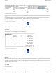
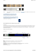
Cover Page 38 of 153 Control Ethernet AC Input Location of the Ethernet and Single AC Connectors at the Rear Panel All signal connections are made via the rear panel. NOTE : Single A.C. PSU version shown. Front Panel Identifying Items Located at the Front Panel The front panel provides a 2 line by 40 character display, 6 buttons, and a red/amber/green tri-colour status LED. Items on the Front Panel LCD Control and status information is displayed on a 2 line by 40 character display.
Cover Page 39 of 153 A technical specification for the connections is given in Technical Specification > Base Chassis. © Ericsson AB 2011. All rights reserved Control Ethernet Overview The Ethernet control ports are used to connect the equipment to nCompass Control [V6.5 on] or to a PC for access to the web browser. Ethernet Ctrl Port Numbering Both connectors share the same IP address, Ctrl1 is the Primary control port, and is by default the active control port.
Cover Page 40 of 153 ☐☐☐☐ Spare Port No Link Off ——————————————— ——— 100 Mbps Flash On x 2 ☐—☐——————☐—☐——— ——— 1000 Mbps Flash On x 3 ☐—☐—☐————☐—☐—☐— ——— The Right LED flash sequence period is 1 s, with the short flash duration being 100 ms. Right (Yellow) LED Link Activity LED Status No Link Off Link On Activity Flash —————————————————— ☐☐☐☐☐☐☐☐☐☐☐☐☐☐☐☐☐☐☐ —☐—☐—☐☐☐☐☐—☐—☐☐—☐☐— © Ericsson AB 2011.
Cover Page 41 of 153 (Unused pins are not connected) Pin 3 - Rx In (+) Pin 6 - RX Out (-) Status and Activity Indication Each Ethernet Data Port has a rear panel mounted status LED associated with it to indicate link status, activity and speed as follows: Left (Green) LED Link Speed LED Status No Link Off 100 Mbps Flash Off x 2 —☐—☐☐☐☐☐☐—☐—☐☐☐☐☐☐ ☐ 1000 Mbps Flash Off x 3 —☐—☐—☐☐☐☐—☐—☐—☐☐☐☐ ☐ —————————————————— The left LED flash sequence period is 1 s, with the short flash duration being 100
Cover Page 42 of 153 AC Power AC Power Inlets AC Input Refer to: Technical Specification > Base Chassis > Power Supply Installing the Equipment > Site Requirements > AC Power Supply Installing the Equipment > External Interfaces > Base Chassis > AC Input Connector © Ericsson AB 2011. All rights reserved USB Connector The USB connector on the front panel of the unit is not for customer use. USB Connector This connector is only used for Test/Maintenance purposes. © Ericsson AB 2011.
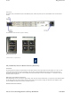
Cover Page 43 of 153 The picture alongside shows the Video input connector: SD-SDI 75 Ω female BNC socket at the module rear panel. Also illustrated is the LED indication for SD SDI lock status. The LED (marked LOCK at the module rear panel) is used to show the status of the module and/or incoming video signal. SD-SDI Input and LOCK Indicator at the Rear Panel LED State Description LED State Description Off The SDI Input is not active. Red The SDI Input is active, but not locked.
Cover Page 44 of 153 Max Input 7 V peak to peak 1.2 V peak to peak Max Current 64 mA 1.6 mA Min Input 0.2 V 0.32 V Cable Shielded Twisted Pair Coax VP/CAB/BAL This enables four balanced AES3 audio channels to be connected to the Audio/Data D-Type connector on a VCM option card. An XLR socket is provided for each of the four digital inputs, and a 75 Ω BNC plug provides an AES3 reference signal at 3.072 Mbps. The reference signal contains a 1 kHz tone at -6 dBFS at a sample rate of 48 kHz.
Cover Page 45 of 153 HD-SDI Input Standard definition digital video can be input via the 75 ohm female BNC connector labeled HD-SDI on the rear panel. See Technical Specification > HD H.264 VCM for further details. The picture alongside shows the Video input connector: HD-SDI 75 Ω female BNC socket at the module rear panel. Also illustrated is the LED indication for HD SDI lock status. The LED (marked LOCK at the module rear panel) is used to show the status of the module and/or incoming video signal.
Cover Page 46 of 153 Connector XLR-3 BNC Impedance 110 Ω 75 Ω Input Level 2-7 V peak to peak 1 V peak to peak Max Input 7 V peak to peak 1.2 V peak to peak Max Current 64 mA 1.6 mA Min Input 0.2 V 0.32 V Cable Shielded Twisted Pair Coax VP/CAB/BAL This enables four balanced AES3 audio channels to be connected to the Audio/Data D-Type connector on a VCM option card. An XLR socket is provided for each of the four digital inputs, and a 75 Ω BNC plug provides an AES3 reference signal at 3.
Cover Note: Page 47 of 153 In this release the ASI outputs are mirrored - the same transport stream is transmitted from both outputs. Two 75 Ω female BNC input connectors are also available but are not supported in this release. ASI Option Module Rear Panel Getting Started Before any communication can be made with the unit the Control IP address needs to be configured. The topics in this section will guide you through the process.
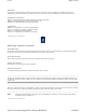
Cover Page 48 of 153 © Ericsson AB 2011. All rights reserved IP Address Restrictions IP Addresses on the unit must adhere to RFC3330 range of restrictions as listed in the following table of allocated IP addresses. Present Use Reference 0.0.0.0/8 Address Block "This" Network [RFC1700, p4] 10.0.0.0/8 Private-Use Networks [RFC1918] 14.0.0.0/8 Public-Data Networks [RFC1700, p181] 24.0.0.0/8 Cable Television Networks --- 39.0.0.0/8 Reserved but subject to allocation [RFC1797] 127.0.0.
Cover Page 49 of 153 Resolution Video and VBI Encoder Bit rate The entered value is the TS rate Buffer Mode Aspect Ratio GOP Length GOP Structure- Field Frame Coding Mode Output Embedded PCR 2) Configure Audio parameters as required Configure > System > Option Slots > Option Slot * > Audio Audio Note : The number of audios available for configuration will depend upon the number of licenses.
Cover Page 50 of 153 If streaming is required from both outputs, configure the other output as previously described. The maximum of 6 streams can be distributed between the 2 outputs. © Ericsson AB 2011. All rights reserved Initial Configuration Within nCC The following topics describe an example for the initial setup of the unit using nCompass Control.
Cover Page 51 of 153 © Ericsson AB 2011. All rights reserved Autodiscovery and Device Connections Summary Autodiscovery Describes how to use to Auto Discovery to find the available units in the range of IP addresses used by the equipment Connections Describes the use of the Connect tool. © Ericsson AB 2011. All rights reserved Autodiscovery Within the Equipment setup: select Auto Discovery and ensure that the range of IP addresses used by the equipment is correct.
Cover Page 52 of 153 Properties Page © Ericsson AB 2011. All rights reserved Connections Using the connect tool, devices can be connected together. NOTE : For the IP output of the Video Processor port 3 is used as the default and nCC will always configure Data port pair 3 and 4. file://C:\Users\ebriacl\AppData\Local\Temp\~hh7DF.
Cover Page 53 of 153 Connections © Ericsson AB 2011. All rights reserved Get Static Parameters To read the Video Processor Static Parameters, the nCC must be in Live Mode Open each device's properties page in turn and select the read static parameters A dialog box indicating success should be returned. Static Parameters At this point it is possible to set certain parameters within the static parameters. These are broken down into sub-sections file://C:\Users\ebriacl\AppData\Local\Temp\~hh7DF.
Cover Page 54 of 153 for modules and host device. Examples of options that maybe updated from here are clock source and SNTP server IP address. Items that are greyed out are not amendable. Static Parameters Properties Static Parameter Editor © Ericsson AB 2011. All rights reserved Configure Multicasts The default addresses will generate details for a source IP address and 6 multicasts. These 6 multicasts are linked to each module within the chassis (for example: slot 1 uses multicast 1).
Cover Page 55 of 153 Multicast Details Configuration Ordering For Video Processors that have the reflex license the reflex support check box must be checked for nCC to route reflex components through the video processor chassis. the remote reflex check box must also be selected in nCC pre 6.8 (between nCC 6.5.5 and 6.8). The default remote reflex delay is 128ms.
Cover Page 56 of 153 Select Component Type © Ericsson AB 2011. All rights reserved First Profile - Video Encoder Type Shows the Select Encoder Type screen Description Tab Fill in the Description tab General Video Configuration Gives general information relating to setting up the video component © Ericsson AB 2011. All rights reserved Encoder Type When creating a video component for the Video Processor, select the 'EN71/8100' option for the encoder type.
Cover Page 57 of 153 Encoder Type © Ericsson AB 2011. All rights reserved Description Tab Complete the description tab file://C:\Users\ebriacl\AppData\Local\Temp\~hh7DF.
Cover Page 58 of 153 Description Tag © Ericsson AB 2011. All rights reserved General Video Configuration Overview Shows the options available on the video tab of the video component configuration pages. Bit rates Shows the bit rate and operational mode options for the video component. VBI/VANC file://C:\Users\ebriacl\AppData\Local\Temp\~hh7DF.
Cover Page 59 of 153 Shows the options available for configuring VBI and VANC Default/Spare Devices Shows the configuration of spare devices. © Ericsson AB 2011. All rights reserved Overview • Most options in the video tab are configured from drop down boxes within the table. Video Tab © Ericsson AB 2011. All rights reserved Bit rates The Bit Rates tab has Seamless Variable options. The 'ViperMPEG2SD' preset sets the delay to 3.
Cover Page 60 of 153 Bit Rates Tab Configure Reflex components (enable statistical multiplexing) file://C:\Users\ebriacl\AppData\Local\Temp\~hh7DF.
Cover Page 61 of 153 Bit Rates Tab - Statistical Multiplexing © Ericsson AB 2011. All rights reserved VBI/VANC VBI settings should be configured through the VBI/VANC tab. The Video Index values must be set to Off if they are not being configured. file://C:\Users\ebriacl\AppData\Local\Temp\~hh7DF.
Cover Page 62 of 153 VBI/VANC Tab © Ericsson AB 2011. All rights reserved Default/Spare Devices Default and Spare devices can be selected from the Default/Spare Devices tab file://C:\Users\ebriacl\AppData\Local\Temp\~hh7DF.
Cover Page 63 of 153 Default/Spare Tab © Ericsson AB 2011. All rights reserved Equipment Status Monitor The Equipment Status Monitor displays the Video Processor units as a mixture of both chassis and modules. file://C:\Users\ebriacl\AppData\Local\Temp\~hh7DF.
Cover Page 64 of 153 Equipment Status Monitor The modules are shown in the bottom half of the device. By right clicking on the device or the modules slightly different options appear. Module level switching is available only when the module is right clicked. Module switching will give a dialog box displaying which modules to be switched from and to. Device switching gives a list of available devices. Available Devices file://C:\Users\ebriacl\AppData\Local\Temp\~hh7DF.
Cover Page 65 of 153 As alarms can be raised against modules and at the device level, there is also a dialog box for configuring module availability. Module Availability © Ericsson AB 2011. All rights reserved Get Static Parameters with Configuration Overview This step is required to make sure that the Static Parameters for the unit are appropriate for the system. This is especially important for systems that have moved between 525 and 625 line configurations.
Cover NOTE : Page 66 of 153 In both the above cases, if static parameters are not re-read, any changes that have been made to the defaults on the encoder will be over-written if nCC is taken off line and then re-started, as the nCC static parameters will be loaded onto the encoder. In the case of the upgraded units, this could result in loss of operation.1. © Ericsson AB 2011.
Cover Page 67 of 153 Multi Video Index The first video module within an encoder card should use the multi_video_idx of 1 Subsequent video modules should increment in value from 1 (i.e. 2, 3, etc.) This range should be the same for all encoder module types, regardless of video encoder type (e.g. MPEG2, H264). Legacy encoder configuration should not change © Ericsson AB 2011.
Cover Page 68 of 153 © Ericsson AB 2011. All rights reserved Transport Stream Output Overview Gives the extent of MPEG-2 compliancy and an overview of the Transport Streams. Describes the TS IP Output Parameters, and states the Transport Stream and Output Data rates. Transport Stream Parameters Tabulates the parameters associated with a transport stream. Transport Stream Control Describes the controls required for each transport stream to be carried by the IP Outputs.
Cover Page 69 of 153 Output Enable Dest. IP Address On IP Output is enabled if the IP destination can be resolved aaa.bbb.ccc.ddd The destination IP address 0 to 65335 Source IP Port [default = 5500] 0 to 65335 Dest.
Cover Page 70 of 153 Transport Stream Control Each transport stream can be carried by the IP Outputs using the following controls. Range Description TS Pkts/UDP Packet Parameter 1 to 7 Number of transport stream packets per UDP packet bit rate 10 kps to 216 Mbps with a resolution of 1 kbps Output transport stream rate Protocol UDP, RTP, RTP/FEC Column, RTP/FEC Column and Row Number of Rows 4 to 20 Number of Columns 1 to 20 Alignment Block Aligned, Non Block Aligned © Ericsson AB 2011.
Cover Alignment Page 71 of 153 Non Block Aligned If the user does not have a license to use FEC then the available IP Encapsulation options become UDP, RTP, RTP/FEC Column (No License) and RTP/FEC Column and Row (No License). If either of the ‘(No License)’ options is selected then IP Encapsulation will be set to RTP and FEC will not be enabled.
Cover Page 72 of 153 Block Aligned linearisation is dealt with in Annex B of the Pro-MPEG Code of Practice. In Block Aligned column FEC packets are sent every D’th frame and the L Column FEC packets are played out every D slots. They are therefore evenly spread over the D*L matrix period. Non Block Aligned linearisation is dealt with in Annex A of the Pro-MPEG Code of Practice. In Non Block Aligned the matrix is ‘skewed’ for the column calculation.
Cover Page 73 of 153 to that video. Only one PCR can be associated with a service. Service Information Tables The SI tables that the system generates for each individual output transport stream can be selected. The following table shows the available levels. SI Level Off PAT/PMT Only Description Elementary streams only PAT/PMT are generated PAT/PMT/CAT/SDT The listed tables are generated. The CAT will be empty as Conditional Access is not supported in this release.
Cover Page 74 of 153 Output Bit Rate The output rate of the transport packets are derived from the 27 MHz reference clock and are accurate to within 1 kbps of the configured bit rate (transport rate). The output video bit rate of the VCM is configurable within ranges dictated by operating mode. The configured video rate means transport rate. The rate control operates on the transport rate. The module supports bit-stuffing to maintain configured bit rate if the operating mode requires it.
NOTE : Cover Page 75 of 153 Packetised Elementary Stream (PES) Packets The Video Encoding module supports adaptation field stuffing of transport packets for the alignment of PES packets to transport packet boundaries. PES streams carry the stream_id = 0xE0. Transport Packet Headers PIDs used in the transport packet headers are configurable and have valid continuity counter values inserted.
Cover Page 76 of 153 User Access Gives information on License keys and User Authentication. Ethernet Control Ports Describes how to configure the Ethernet Control Ports. Ethernet Data Ports Describes how to configure the Ethernet Data Ports. Option Modules Gives information relating to the operation and control of the option modules. Current Configuration Describes how the current configuration is held. Data Routing Describes aspects of data packet routing.
Cover Page 77 of 153 Front Panel Describes various aspects associated with the front panel display and controls. Introduction Introduces the elements located on the front panel. Also describes how to reset the unit. Navigate Mode Describes the meaning and use of Navigate Mode. Edit Mode Describes the meaning and use of Navigate Mode. Front Panel Menus Illustrates the menus available using the front panel display and pushbuttons. © Ericsson AB 2011.
Cover Page 78 of 153 Navigate Mode Navigate mode allows the user to move between menus and pages within menus. The pushbuttons contain LEDs which are updated to indicate which pushbutton presses are valid as each navigation event is processed. For example, an illuminated Up arrow pushbutton indicates there are pages above the current one, whilst a pushbutton that is not illuminated does not link to any additional pages or information.
Cover Page 79 of 153 Front Panel Menus To navigate to the next level of menus press the right arrow key. The front panel menu structure is as follows: Top Level Menu To navigate to the next level of menus press the right arrow key. To return to the top Use the up and down level menu press arrow keys to move the left arrow key. between these menus. To access these parameters press the right arrow key, and then the up and down arrow keys to move between parameters.
Cover Page 80 of 153 © Ericsson AB 2011. All rights reserved Ethernet: Control Overview The Base Chassis has two Ethernet control ports that support IEEE 802.3 100BASE-TX and 1000BASE-T protocols. The control ports are accessible via RJ-45 connectors mounted on the rear panel of the unit. Ethernet Control Port Numbering The Ethernet control ports are used to connect the unit to a web browser or the control system (nCompass Control [V6.5 onwards]).
Cover Page 81 of 153 subnet © Ericsson AB 2011. All rights reserved Ethernet Data Ports Four gigabit Ethernet ports are provided for data input and output. Data Ethernet Describes the physical Ethernet ports, and how the ports can be configured. Data Input Describes the message type supported. Data Output IP encapsulated transport streams can be transmitted from the unit. Data Port Redundancy Describes how Ethernet data port redundancy can be achieved. © Ericsson AB 2011.
Cover Page 82 of 153 aa:bb:cc:dd:ee:ff Gex port’s MAC address (This cannot be changed by the user) Link Up (1000) Link up and link speed 1000 Mbps Link Up (100) Link up and link speed 100 Mbps Link Down Link Down days : hours : mins : secs The length of time that the link has been up.
Cover Page 83 of 153 Data Network Redundancy Redundancy NOTE : Both outputs of a pair are active at the same time, therefore the use of primary and secondary ports is meaningless in this configuration. The four Ethernet data ports operate as two redundant pairs. Data 1 and 2 (Ge1 with Ge2), and Data 3 and 4 (Ge3 with Ge4). When an output transport stream is defined, it is assigned by the user to one or other data output pairs. Both ports are independent of each other i.e.
Cover Page 84 of 153 The configuration of an output transport stream can be divided into the following groups: Components Transport Stream Service Components Components are generated by the option cards. A single component from an option card can be assigned to up to 8 services. See the sections describing each option card for details of how to configure each type of component.
Cover Page 85 of 153 Configuring Option Cards EN7100 SD MPEG-2 VCM (VP/HWO/EN7100/ENC) Describes setting up the VP/HWO/WN7100/ENC Option Module. EN8100 SD MPEG-2 VCM (VP/HWO/EN8100/ENC) Describes setting up the VP/HWO/WN8100/ENC Option Module. EN8130 SD H.264 VCM (VP/HWO/EN8130/ENC) Describes setting up the VP/HWO/WN8130/ENC Option Module. EN8180 HD MPEG-2 VCM (VP/HWO/EN8180/ENC) Describes setting up the VP/HWO/WN8180/ENC Option Module. EN8190 HD H.
Cover Page 86 of 153 Video Component Configuration The video configuration can be broken down in to the following sections: Video Input and Pre-Processing Details the parameters that define the video input, and the processing of the video prior to it being encoded. Video Encoding Details the parameters that define the video encoding. Video Stream Output Details the parameters to be included in the video stream output.
Cover Page 87 of 153 © Ericsson AB 2011. All rights reserved Video Encoding Video Encoder Profile 4:2:0 MP@ML Video Bit rate Value entered is the TS rate Buffer Mode Constant Bit rate or Seamless (for Reflex operation) Aspect Ratio Does not effect the video encoding but rather indicates what the desired aspect ratio for the decoded picture (not the pixel). If no other mechanism such as WSS in the VBI is used, the video output image will use this aspect ratio.
Cover Page 88 of 153 © Ericsson AB 2011. All rights reserved Vertical Blanking Interval Data Configuration VBI Controls if the Aspect ratio/AFD data will be by the Video Index. Video Index The default lines are set to decode Video Index (11/324 in 25Hz, 14/277 in 29.97 Hz) The User can define the lines used to decode Video Index.
Cover Page 89 of 153 Dolby Metadata Presets These presets can be applied to any channel encoding audio into the Dolby Digital audio standard. Dolby E Transcode This details how to configure an audio decoder and re-encode the decoded output. © Ericsson AB 2011. All rights reserved Audio Input Parameter Description Input Source Sets the source used by the audio encoder. Input Source Options This controls which input is used for the audio encoder.
Cover NOTE : Page 90 of 153 Dolby Digital MPEG-1 Layer II HE-AAC DD Pass Thru Passthrough of pre-encoded Dolby Digital Audio DolbyE Pass Thru Passthrough of pre-encoded DolbyE Audio LPCM Pass Thru Passthrough of uncompressed Audio (Linear PCM) Audio Descr Service MPEG1 Layer II encode of a mono audio track that describes action in the video plus a control track By default the PMT descriptor used for Dolby Digital is that defined by DVB.
Cover DD Plus Pass Thru DolbyE Pass Thru Page 91 of 153 Embedded PCR Lipsync Offset Configure a delay to the audio to improve A/V synchronisation Embedded PCR Sets PCR to be embedded in the audio stream or on a separate PID AU Ctrl Controls the data put into the TS for audio Access Units (AU). AU info is defined in ETSI 101 154.
Cover Page 92 of 153 Center mix level Indicates the downmix level when there is no centre speaker. This is applied to left and right channels only. Surround mix level Surround downmix level for the front left and right channels when consumer has no surround speakers.
Cover Decoder Type Page 93 of 153 Can only be set to ‘Dolby E’ at present. When set to ‘On’, the main input is passed through to program outputs 1-4 if compressed audio is not detected at the input (see diagram below). PCM Bypass When set to ‘Off’, program outputs 1-4 are replaced with silence if compressed audio is not detected at the input. Program outputs 5-8 are always replaced with silence when compressed audio is not detected at the input.
Cover Page 94 of 153 When set to ‘Off’, the user-specified coding mode always applies. For example if the coding mode is set to 2/0 and the decoder output is 5.1, a downmix from 5.1 to 2/0 will be performed. Determine which metadata parameters are overridden by preset metadata, even if live metadata is present. ‘Off’ will always use the decoder metadata (if present). Override Metadata Parameters ‘All’ will override all metadata parameters with the user-specified metadata preset.
Cover Page 95 of 153 Audio Component Configuration NOTE: Changes to the configuration of the unit can cause the output to be interrupted while the new settings take effect. See Technical Specifications > EN* VCM > Video > Operating Times for more information. © Ericsson AB 2011.
Cover Page 96 of 153 Video Input Format SD 29.97 Hz The video input is expected to be 29.97 Hz frame rate (525 line NTSC) Horizontal Video Bandwidth 30 to 100 % Sets the video horizontal bandwidth filter. Enables or disables Motion Compensated Temporal Filtering. MCTF (Requires the VP/SWO/SD/MCTF license) Stills Detection On/Off Detects if the video is a still picture, and if the unit is operating under Reflex control, it will request Bmin when a still is detected.
Cover Page 97 of 153 stream. GOP Structure IP, IBP, IBBP, IBBBP Sets the number of B frames between reference frames Scene Cut Detection On, Off Configuration to minimise affects caused by scene changes. An I-Frame will be inserted on scene changes, changing GOP length.
Cover Page 98 of 153 On (Default) lines. These are lines 11 and 324 in 25 Hz and 14 and 277 in 29.97 Hz On (User) Video Index extraction is enabled, but the user must specify the VBI lines from which it is to be extracted. Video Index Field 1 Valid VBI Line (dependant on the selected video input format) The field 1 VBI line to extract Video Index from when Video Index is On (User).
Cover Page 99 of 153 © Ericsson AB 2011. All rights reserved EN8180 HD MPEG-2 VCM (VP/HWO/EN8180/ENC) The following topics describe the setting up of the VP/HWO/EN8130/ENC Video and Audio components. Video Component Configuration Audio Component Configuration NOTE: Changes to the configuration of the unit can cause the output to be interrupted while the new settings take effect. See Technical Specifications > EN* VCM > Video > Operating Times for more information. © Ericsson AB 2011.
Cover Page 100 of 153 Source Output On Video Loss SDI The video will be sourced from the SDI input on the rear panel. Color Bars An internally generated color bars test pattern will be used as the video source. Black An internally generated black test pattern will be used as the video source. Moving Object An internally generated moving object test pattern will be used as the video source. Freeze Frame Repeat the last good video frame on loss of video input.
Cover GOP Structure Page 101 of 153 IP, IBP, IBBP, IBBBP Sets the number of B frames between reference frames Scene Cut Detection On, Off Configuration to minimise affects caused by scene changes. An I-Frame will be inserted on scene changes, changing GOP length.
Cover Page 102 of 153 The maximum bit rate allocated for the ANC data can be set, up to a maximum of 2 MBit/s. If the incoming ANC data rate exceeds this an alarm will be raised. Max ANC Bit Rate Time Code Control TC Mode Controls what mode the Time code (TC) is working in, either Off, external source or internally generated.
Cover Page 103 of 153 Vertical Blanking Interval/Ancillary Data Configuration Details the parameters that define the VBI/ANC configuration. © Ericsson AB 2011. All rights reserved Video Input and Pre-Processing Pre-Processor Parameter Description Output On Video Loss Controls the action taken when the video input is not locked to a video source of the defined frame rate. Source Sets the video source used by the video encoder.
Cover GOP Structure Page 104 of 153 Sets the number of B frames between reference frames Scene Cut Detection Configuration to minimise affects caused by scene changes Reflex Reflex license required to enable configuration Seamless Buffer Delay Buffer Delay for Reflex operation Min Seamless Bit rate Min bit rate for reflex operation Lookahead Delay The time between the lookahead encoder estimating the required bit rate and the final encoder encoding that piece of video.
Cover Page 105 of 153 © Ericsson AB 2011. All rights reserved Current Configuration The Host Controller maintains a copy of the current system configuration in flash memory. On system re-start, this current system configuration is restored, so the system returns to its previous state.
Cover Page 106 of 153 © Ericsson AB 2011. All rights reserved Temperature Monitoring Overview Temperatures are reported to the user in degrees Celcius (° C) and degrees Fahrenheit (° F). Host Card Monitoring The die temperature of the main components on the Host card are monitored, and reported to an accuracy of ±2 ° C. A host card temperature alarm threshold can be set that, if exceeded, causes a ‘System Over Temperature’ Alarm to be generated.
Cover Page 107 of 153 © Ericsson AB 2011. All rights reserved Simple Network Management Protocol [SNMP] Supported Protocols SNMP versions 1, 2c and 3 are supported, primarily for alarm trap handling. The General EricssonTelevision MIB is also supported. NOTE: The unit does not support control via SNMP, all remote control is via HTTP or HTTPS. Operation The unit’s SNMP functionality can be enabled or disabled, with up to five IP addresses assigned for any SNMP Trap message to be sent.
Cover Page 108 of 153 Looking After The Unit This section details routine maintenance tasks to be performed by the operator and provides general servicing advice and faultfinding information. It also provides information regarding warranty and maintenance available from Customer Services and gives relevant disposal information.
Cover Page 109 of 153 Cleaning Unplug the unit from the wall outlet before cleaning the exterior with a damp cloth. Do not use liquid cleaners or aerosol cleaners. NOTE : Only the exterior of the case should be cleaned. © Ericsson AB 2011. All rights reserved Servicing Damage Requiring Service WARNING! Do not attempt to service this product as opening or removing covers may expose dangerous voltages or other hazards. Refer all servicing to service personnel who have been authorised by Ericsson.
Cover Page 110 of 153 All Ericsson Television Products and Systems are designed and built to the highest standards and are covered under a comprehensive 12 month warranty. Levels of Continuing Ericsson Service Support For stand-alone equipment, then Ericsson’s BASIC Essential support is the value for money choice for you. BASIC provides you with year-by-year Service long after the warranty has expired. For systems support you can choose either Gold Business Critical support or Silver Business Advantage.
Cover Page 111 of 153 Do not remove the covers of this equipment. Hazardous voltages are present within this equipment and may be exposed if the covers are removed. Only Ericsson Television trained and approved service engineers are permitted to service this equipment. CAUTION! Do not remove the covers of this equipment. Unauthorised maintenance or the use of non-approved replacements amy affect the equipment specification and invalidate any warranties.
Cover Page 112 of 153 To replace the AC power fuse: 1. Ensure that power is turned off and the power cable is disconnected from the AC power inlet. 2. Ease out the fuse carrier by placing a small, flat-bladed screwdriver in the notch at the top of the carrier. CAUTION! When replacing the power input fuse, always ensure that a fuse of the correct type and rating is fitted. Failure to do so results in inadequate protection. 3. Replace the fuse in the carrier. 4.
Cover Page 113 of 153 © Ericsson AB 2011. All rights reserved Alarms The chassis can report any error condition by generating an alarm event. Alarms are reported on the web page of the chassis, and can also be reported by the generation of SNMP traps. Every alarm event type is assigned a severity level, the possible alarm severity levels are: masked, warning, minor, major, and critical. If an alarm is masked, the alarm event causes no action.
Cover Page 114 of 153 generate the required trap messages for any change in alarm states. The IP address to send SNMP trap messages to can be configured by the operator (see Operation and Control: SNMP). The list of currently active alarms can also be accessed via the front panel. © Ericsson AB 2011. All rights reserved Alarms - Control Port The control ports can raise an alarm during abnormal operational conditions.
Cover Page 115 of 153 The VCM endeavours to self monitor itself for correct operation and correct any inconsistencies it finds. This includes the resetting of malfunctioning sub-systems or the whole card if necessary. The module attempts to maintain correct operation to minimise the effects of faults. All such actions are reported through the alarms/status/logging back to the host card. Module Responses The Host card monitors all responses back from the module and resets the module if appropriate.
Cover Page 116 of 153 the LED/LCD Display itself is probably at fault. Call a Service Engineer. 1 Is the unit still working but the LED/LCD display inactive? 2 Check Power Source. Connect a known, working piece of The problem lies within the unit or power equipment to the power source cable. Proceed to next step. outlet. Does it work? The problem lies with the power source. Check building circuit breakers, fuse boxes, etc. If problem persists, contact the electricity supplier.
Cover Page 117 of 153 Time and Date Any changes to the time and date are recorded in the system log. © Ericsson AB 2011. All rights reserved Software and Firmware Upgrade Generally an Upgrade Wizard will be provided to upgrade the unit software and firmware via the Ethernet control port. In the event of a failed upgrade, it is possible to “re-boot” the system to such a level to allow software and firmware to be loaded on to it. In this case, contact Customer Support for assistance. © Ericsson AB 2011.
Cover Page 118 of 153 Technical Specification Base Chassis Details the technical specification of the basic chassis. SD MPEG-2 VCM Details the technical specification of the SD MPEG-2 VCM. SD H.264 VCM Details the technical specification of the SD H.264 VCM. HD MPEG-2 VCM Details the technical specification of the HD MPEG-2 VCM. HD H.264 VCM Details the technical specification of the HD H.264 VCM. ASI I/O Module Details the technical specification of the Ext Sync Module.
Cover Page 119 of 153 Physical Details Item Specification Height 44.5 mm chassis Width 442.5 mm excluding fixing brackets Overall width 482.6 mm including fixing brackets Depth 550 mm excluding rear connector clearance Rack mounting standard 1U x 19 inch (1U = 44.45mm) Approximate weight 7.5 kg (16.5 lbs) © Ericsson AB 2011. All rights reserved Power Supplies A.C Mains Input This equipment is fitted with a wide-ranging power supply.
Cover Page 120 of 153 A technical earth terminal is located at the rear panel of the chassis. © Ericsson AB 2011. All rights reserved IP Output Transport Stream The following parameters are controllable for each IP Output transport stream for each output port or ports depending on the redundancy mode that is selected: Description/Range Comment Source IP Address Parameter aaa.bbb.ccc.ddd Source IP address Subnet Mask aaa.bbb.ccc.
Cover NOTE : Page 121 of 153 The front panel always provides a way of changing these settings to prevent all control interfaces being disabled. MAC Address The MAC address of each Ethernet Control port can be assigned via the Static Parameters table. © Ericsson AB 2011. All rights reserved Data Ethernet Specification Overview The Ethernet Data ports support IEEE 802.3u auto-negotiation and parallel detection.
Cover Page 122 of 153 The MAC address of each Ethernet Control port can be assigned via the Static Parameters table. It is not possible to set the MAC addresses of each of the Ethernet Data ports to the same value. © Ericsson AB 2011. All rights reserved SD MPEG-2 VCM Technical Specification - EN8100 and EN7100 SDI Input Defines the parameters for the SDI IN connector. Digital Audio Input Defines the Audio input and the associated parameters.
Cover Page 123 of 153 Input Level 800mV pk-pk nominal ±10% Return Loss Better than 15 dB, 10 MHz - 270 MHz Input Impedance 75 Ω (powered-down impedance = 75 Ω) © Ericsson AB 2011. All rights reserved Digital Audio Specification Audio Input The digital input of the VCM accepts four stereo pairs of digital audio. The available encoding options depend upon the licenses enabled.
Cover Page 124 of 153 Video Formats Active Video Start Line The active video starts on line 23 for both 525-line and 625-line (SMPTE RP 202-2000). Video Resizing The unit supports the input of video at 720x576, 25 Hz and 720x480, 29.97 Hz. The following re-sampling of any input format is supported: 29.97 Hz input format Process 720x576@25 (pass through) 25 Hz input format 720x480@29.97 (pass through) Scale 1/1 704x576@25 704x480@29.
Cover Page 125 of 153 Pass Through Modes Describes the supported audio pass through options. Audio Test Tone © Ericsson AB 2011. All rights reserved Encoding Stereo The VCMs audio module codes up to eight channel pairs of the following listed coding standards. Coding Standard Dolby Digital MPEG Layer 2 Maximum Number Description Comments 2 Dolby Digital Stereo Encoding Only available when /SWO/DOLBY/AC3 has been purchased - 1 license required per channel pair.
Cover Page 126 of 153 This option is available for MPEG-1 Layer II only. This applies a technique called intensity coding. The human ear is not as good at locating higher frequencies as it is lower ones. The use of this mode may introduce more artefacts than stereo. Stereo [2/0] This mode treats the incoming audio signal as a left and right channel that the viewer will listen to simultaneously.
Cover Page 127 of 153 96 √ √ 112 √ √ 128 √ √ 160 √ √ 192 √ √ 224 √ √ 256 √ √ 320 √ √ 384 √ √ 448 √ √ 512 √ √ 576 √ √ 640 √ √ © Ericsson AB 2011. All rights reserved Pass Through Modes Clocking For the best performance when passing through compressed audio the video and audio coming into the unit must be locked together, and the system clock locked to ‘Video’ or ‘Ext SYNC’. When set to ‘Ext SYNC’the audio and video must also be locked to this source.
Cover Page 128 of 153 SD H.264 VCM Technical Specification - EN8130 SDI Input Defines the parameters for the SDI IN connector. Digital Audio Input Defines the Audio input and the associated parameters. Audio Defines the modes of audio operation © Ericsson AB 2011. All rights reserved HD MPEG-2 VCM Technical Specification HD-SDI Input Defines the parameters for the HD-SDI IN connector. Digital Audio Input Defines the Audio input and the associated parameters.
Cover Connector Type Page 129 of 153 75 Ω BNC female socket Input Standard ANSI / SMPTE 292M Cable length 150m maximum from a source with an output level 800 mV pk-pk nominal ±10% Input Level 800mV pk-pk nominal ±10% Return Loss Better than 15 dB, 5 MHz - 1.5 GHz Input Impedance 75 Ω (powered-down impedance = 75 Ω) © Ericsson AB 2011. All rights reserved HD H.264 VCM Technical Specification HD-SDI Input Defines the parameters for the HD-SDI IN connector.
Cover Page 130 of 153 External Sync Module Technical Specification The External Sync Option card provides a means of inputting a system reference either from an external, 10MHz clock or analog video source. Only one reference source may be connected at any time, and the single BNC connector caters for either input signal type.
Cover Page 131 of 153 Clock and Timing This section describes the use of derived and real time clocks throughout the unit. Redundancy Modes This section gives information relating to the various redundancy functions available. Alarm Lists Provides information about the alarms that can be generated by the unit. © Ericsson AB 2011.
Cover Page 132 of 153 transport stream. The AES stream can contain non-audio data as well as uncompressed audio. This mechanism can be used to carry Linear PCM audio, or Dolby E data. Dolby E Dolby E was developed by Dolby Laboratories. It allows up to 8 channels of Dolby E compressed audio to be distributed over an existing 2 channel digital infrastructure. The compression applied is less than that for consumer codecs (i.e.
Cover Page 133 of 153 Option Cards Available Option Cards Tabulates the option cards available at this release. Handling Option Cards This section gives information relating to the handling of Option Modules as they are inserted/removed from the unit. Option Card Hot Swap This section gives an overview of the way the host checks the availability of an option module. Option Card Plug and Play This section gives an overview of the plug and play concept used in the unit. © Ericsson AB 2011.
Cover Page 134 of 153 Gives guidance relating to the care and handling of Option Cards. Adding an Option Card Gives information relating to adding an Option Module and how to check the operation was successful. Removing an Option Card This page details what to do when it is desired to remove (and not replace) an option card. Replacing an Option Card Gives information relating to the replacing of an Option Module and how to check the operation was successful. © Ericsson AB 2011.
Cover Page 135 of 153 Do not touch solder joints, pins, or exposed printed circuitry. Do not leave the Option Card where others can handle and possibly damage it. While the Option Card is still in its anti-static package, touch it to an unpainted metal part of the system unit for at least two seconds. (This drains static electricity from the package and from your body.) Remove the Option Card from its package and install it directly into your base chassis without setting it down.
Cover Page 136 of 153 raised. If all options are reported correctly, the “accept option slot configuration” needs to be applied. This will accept the new hardware configuration and clear the alarm. © Ericsson AB 2011. All rights reserved Replacing an Option Card A failed option card can be replaced without powering down the base chassis, i.e. can be ‘hot-swapped’. 1. To perform a hot-swap the option cards should only be unplugged or inserted when the chassis is fully booted and configured. 2.
Cover Page 137 of 153 an option card is contained on the option card itself. A good example of this is MPEG SI generation. The Host controller provides the functionality to generate and play out the SI required by a transport stream. However a VCM is required to provide any descriptors required for any elementary stream types that it generates. © Ericsson AB 2011.
Cover Page 138 of 153 Electromagnetic Compatibility (EMC) The equipment has been designed and tested to meet the following: EN 55022 and CISPR22 International EN 61000-3-2 European Electromagnetic Compatibility (EMC), Part 3 Limits; Section 2. Limits for harmonic current emissions (equipment input current up to and including 16 A per phase) EN 61000-3-3 European Electromagnetic Compatibility (EMC), Part 3. Limits; Section 3.
Cover Page 139 of 153 Materials Declarations EricssonTelevision products are designed and manufactured in keeping with good environmental practise. Our component and materials selection policy prohibits the use of a range of potentially hazardous materials. In addition, we comply with relevant environmental legislation. For the European Union For product sold into the EU after 1st July 2006, we comply with the EU RoHS Directive. We also comply with the WEEE Directive.
Cover Page 140 of 153 Protect from moisture See CE Marking See C-Tick Mark Defines country of origin The packaging is reusable per GB 18455-2001 This symbol guarantees that packaging with this symbol is recyclable and will be accepted by cardboard recyclers Recyclable per GB 18455-2001 © Ericsson AB 2011. All rights reserved Safety Compliance General This equipment has been designed and tested to meet the requirements of the following: EN 60950-1 European Information technology equipment - Safety.
Cover Page 141 of 153 Program Clock Reference The MPEG Standard defines a Program Clock Reference (PCR) to be included in a transport stream to allow a decoder to lock to the 27 MHz clock being used by the encoder. The DVB standards require a PCR to be present in a transport stream every 40 ms or less, (but it is possible to configure the unit to generate PCRs less frequently). The PCR can be embedded in a component PID, (i.e. video or audio), or it can be carried on its own PID.
Cover Page 142 of 153 the time and date are recorded in the system log. The real time clock is used to set the time and date when the unit is started, but then its own time and date is maintained, unless a change to the time and date parameters occur, when it will be updated to the new settings. The system can set or correct its system clock from information received from an SNTP Time Server.
Cover Page 143 of 153 Chassis Critical Alarm If a Chassis Critical alarm is asserted, or if nCC loses communications with the chassis, nCC will switch all the outputs generated in the failed chassis to a suitable spare chassis if one is available. © Ericsson AB 2011. All rights reserved Control Network Redundancy Overview The control network is assigned to the physical Ethernet ports Ctrl1 and Ctrl2. The lower number port of the pair is considered to be the primary port, and the other the spare.
Cover Page 144 of 153 MPEG Layer The MPEG-2/DVB layer is specified in ISO/IEC IS 13818 “Generic Coding of Moving Pictures and Associated Audio”. The main functionality of this layer is to transform MPTS (Multi-Program Transport Streams) into a number of SPTS (Single-Program Transport Streams). A transport stream carrying multiple programs is in this way split into a number of ‘mini’ transport streams, each carrying a single program.
Cover Page 145 of 153 Ethernet Layer The data link layer is Ethernet according to IEEE 802.3/802.3u (auto sensing 10/100 Mbps, Twisted Pair, RJ-45 connector). IP Overhead The IP overhead calculation when mapping MPEG-2 TS packets into IP frames is shown in the following table. Overhead factor Comments MPEG-2 TS 1.0 UDP 1324/1316 = 1.006 IP 1344/1324 = 1.015 IP header=20 bytes 1358/1344 = 1.010 Eth header=14 bytes Ethernet UDP header=8 bytes Total overhead factor becomes: 1.006 x 1.015 x 1.
Cover Page 146 of 153 Over Temperature Base Unit Host 0 00000443 1091 Power On Self Test Failure Base Unit Host 0 00000444 1092 +12V A Failed Base Unit Host 0 00000445 1093 +12V B Failed Base Unit Host 0 00000446 1094 Real Time Clock Base Unit Host 0 00000447 1095 NTP Server Response Timeout Base Unit Host 0 00000448 1096 Internal Hardware Issue Base Unit Host 0 00000449 1097 Host Build Version Mismatch Base Unit Host 0 0000044A 1098 correctly, and that the ambient
Cover System Clock Not Locked Page 147 of 153 Base Unit Host 0 0000044B 1099 Chassis Identity Not Programmed Base Unit Host 0 0000044C 1100 Selected Mux SCR Source is not present Base Unit Host 0 0000044D 1101 Host Identity Not Programmed Base Unit Host 0 0000044E 1102 Uncontrolled release Base Unit Host 0 0000044F 1103 Option card failed to boot Base Unit Slot 1 to Slot 6 0 00000421 1057 Option Card Comms Failure in slot Base Unit Slot 1 to Slot 6 0 00000422 1058 HW Configur
Cover Page 148 of 153 Referenced Output Stream Unavailable Base Unit Slot 1 to Slot 6 0 00000461 1121 card is not installed in the specified slot or it internal cannot provide the requested output stream. © Ericsson AB 2011. All rights reserved HD H.264 VCM Alarms - EN8190 The following table lists the alarm and failure identifiers generated by the HD H.264 VCM. HD H.
Cover Page 149 of 153 Audio1 ADS Control Track Audio Module Slot 3 0 000C0043 786499 input Audio1 silence Audio Module Slot 3 0 000C0044 786500 input Audio Module Slot 3 0 000C0045 786501 input Audio Module Slot 3 0 000C0051 786513 input Audio2 Input Lock Audio Module Slot 3 0 000C0052 786514 input Audio2 ADS Control Track Audio Module Slot 3 0 000C0053 786515 input Audio2 silence Audio Module Slot 3 0 000C0054 786516 input Audio Module Slot 3 0 000C0055 786517 input Audio Modu
Cover Page 150 of 153 Audio8 Input Lock Audio Module Slot 3 0 Audio8 ADS Audio Module Slot 3 0 Control Track 000C00B2 786610 input 000C00B3 786611 input Audio8 silence Audio Module Slot 3 0 000C00B4 786612 input Audio8 loss of metadata Audio Module Slot 3 0 000C00B5 786613 input Port ID (hex) ID (dec) Type Please check source connection. Control track for Audio Description not present Silent period detected. Valid only for Audio Description Service encoding.
Cover Temperature Invalid Parameter Video/Audio Module Error Power On Self Test Failure Internal HW Information Option Card Build Version Mismatch SMPTE334 Closed Captions Input Lock Anc Bar Data Input Lock Video Input Lock Page 151 of 153 Coding Module MPEG2 Video Coding Module MPEG2 Video Coding Module MPEG2 Video Coding Module MPEG2 Video Coding Module MPEG2 Video Coding Module MPEG2 Video Coding Module MPEG2 Video Coding Module MPEG2 Video Coding Module Please switch off and refer to Customer S
Cover metadata Audio2 DD Pass Thru sync loss Audio2 Input Lock Audio2 ADS Control Track Audio2 silence Audio2 loss of metadata Audio3 DD Pass Thru sync loss Audio3 Input Lock Audio3 ADS Control Track Audio3 silence Audio3 loss of metadata Audio4 DD Pass Thru sync loss Audio4 Input Lock Audio4 ADS Control Track Audio4 silence Audio4 loss of metadata Audio5 DD Pass Thru sync loss Audio5 Input Lock Audio5 ADS Control Track Audio5 silence Audio5 loss of metadata Audio6 DD Pass Thru sync loss Audio6 Input Lock
Cover metadata Page 153 of 153 Module Slot n 0 000A00B5 655541 input stop encoding on loss. © Ericsson AB 2011. All rights reserved ASI Option Module Alarms The following table lists the alarm and failure identifiers generated by the ASI option module.