
User guide


Installing and Powering Up
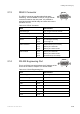
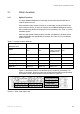
2.13 RELAY Connector
The RELAY connector provides alarm/fault status
monitoring. This is available via a 9-pin, D-type female
connector located on the rear panel. It is possible to
exercise the alarm and fail relays to ensure their correct
operation via nCC.
Table 2.22 RELAY Connector
RELAY
Item Specification
Connector type 9-pin, D-type connector, female
Connector designation RELAY
Ground Pin 1 0 V
Reset Pin 5
Pin 9
+5 V through Fault relay
0 V through 5 Ω
Alarm Contacts Pin 2
Pin 3
Pin 4
Alarm Common (5 Ω in series)
Make to pin 2 when OK
Make to pin 2 when not OK
Fail Contacts Pin 6
Pin 7
Pin 8
Make to pin 8 when OK
Make to pin 8 when not OK
Fail Common (5 Ω in series)
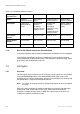
RS232
2.14 RS-232 Engineering Port
This is an RS-232 port which allows the IP Address of the
unit to be set. Refer to Chapter 4 for further details.
Table 2.23 RS-232 Engineering Port
Item Specification
Connector type 9-pin, D-type connector, male
Connector designation RS-232
RXD: Pin 2
TXD: Pin 3
DTR: Pin 4
0V: Pin 5
RTS: Pin 7 Pins 7 and 8 connected
CTS: Pin 8
2/1553-FGC 101 1014 Uen B
2-29